Your cart is currently empty!
How to Set Up your Maple Modular PLC as a Modbus TCP Master Device
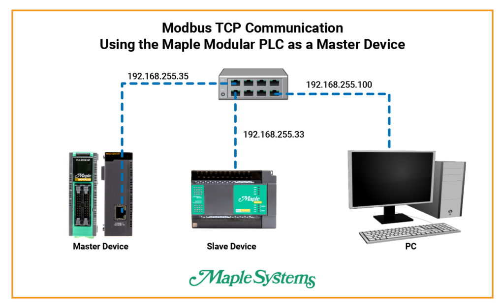
This tutorial will cover Modbus TCP communication between two Maple PLC’s using an Ethernet Module. A Maple Modular PLC as the master device and a Maple Micro PLC as a slave device.
Software Required
Hardware Required
- Maple Modular PLC’S – Any Maple Modular PLC can be used.
- Maple Micro PLC’S – Any Maple Micro PLC can be used.
- MOD-SENT01-Ethernet Module
* The Maple Modular PLC DOES have Modbus TCP Master capabilities but you have to use the MOD-SENT01 Ethernet module to to do this. In this tutorial, it will be an example using a Maple Modular PLC as the Modbus TCP Master device and a Maple Micro PLC as the TCP Slave Device.
Note: All of the Maple Modular PLC’s can be a Modbus TCP Master device by using the MOD-SENT01 Ethernet Module.
Modbus TCP Network Configuration

Use an ethernet switch to communicate between a Maple Modular PLC as the Modbus TCP Master device to another Maple PLC as the TCP Slave device. Make the sure the IP address is on the same subnet but the last octet is different.
Modbus TCP Master Configuration (Maple Modular PLC)

- In your Modbus TCP Master project right click on Program
- New Program
- Choose MODBUS/TCP MASTER
- Name your program
- Choose an ID number
- Click OK

A Special Function window will open.
- Next, click New to enter the Modbus Slave IP address (Maple Micro PLC)
- Make sure the IP address shares the same subnet as the master device but the last octet is different
- Click OK
- Next, make sure the slot number is slot 1, which is the Ethernet Module
- Click Save

Next add a Data Block to communicate with the Analog Input Channel on the slave device
- Click Add
- Choose the function “03 Read Holding Registers (4x)
- PLC device will be register D00
- After setting up the function, click “Save”

Next configure your Modbus TCP Master IP address
- Under Parameter, double click on PLC Parameter
- Click the Ethernet tab
- Enter the Modbus Master IP address – The IP address should share the same subnet as the slave device except for the last octet.
- Click OK

Next configure your MOD-SENT01 Ethernet Module
- You will need to be online to configure your MOD-SENT01
- For Slot: Select Slot1 as this is the slot number for the Ethernet Module
- Make sure the IP address matches the TCP Master Device
- Set the MODBUS Unit ID to 1
- Click “Write” to communicate with the slave device (Micro PLC).
Modbus TCP Slave Configuration (Maple Micro PLC)

First, configure the analog input channel
- Go to Parameter and double click PLC Parameter
- Click the Analog I/O tab
- Change the device setting to D0
- Configure Analog Input – Ch. 1
- Switch from Disable to Enable
- Input : 0-5V
- Click OK

Next configure your Modbus TCP Slave IP address
- Under Parameter, double click on PLC Parameter
- Click the Ethernet tab
- Enter the Modbus Slave IP address – The IP address should share the same subnet as the master device except for the last octet.
- Click OK
Online Communication
Maple Modular PLC Online – Master Device

Maple Micro PLC Online – Slave Device

Sample Project
The project shown above was designed for the specific hardware mentioned at the beginning of the tutorial and is intended to provide you guidance when programming your unit. If you are using models other than the ones specified in this sample project, similar steps can be duplicated within your own project.
Download MapleLogic Sample Project (Slave Device Project)
Download MapleLogic Sample Project (Master Device Project)
Resources & Documentation
Maple PLC/MapleLogic Resources
More
Tutorials
Sample Projects
See our Support Center for a complete list of Quick Start and Installation Guides
About the Author
