This tutorial will demonstrate how to read temperature with a thermocouple using a Maple Modular PLC and a Thermocouple Module in MapleLogic.
Software Required
Hardware Required
- Maple Modular PLC’S – Any Maple Modular PLC can be used.
- IO-SA0400T – Thermocouple Module
- Hollow Tube Thermocouples – You can configure K,J,E,T,R,S,B,N Thermocouples in MapleLogic
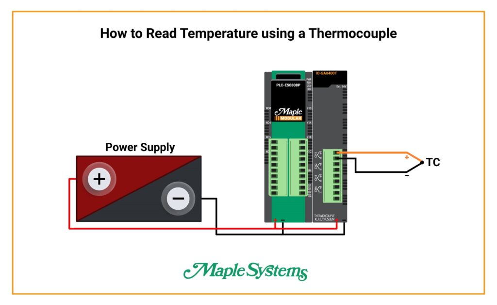
Wiring Diagram
Ladder Diagram
After starting a new scanned program in MapleLogic, here is a simple method in communicating with a PLC and Thermocouple Module using Ladder Diagram.
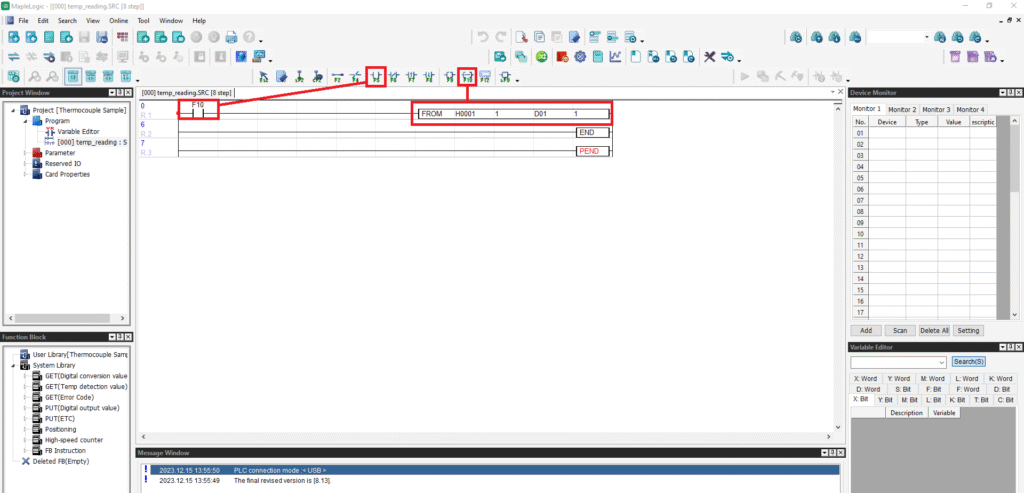
- Use the “Always ON” system bit (F10) to turn ON the application instruction for the Thermocouple Module.
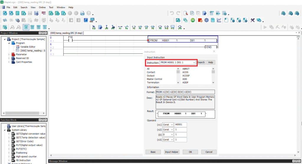
- FROM: Refers to Analog Input communication.
- H0001: Refers to Slot 1 on your Chassis.
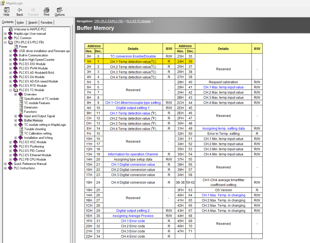
- 1: Refers to Channel 1 on the Thermocouple Module according to the buffer memory.
- D01: Stored in this memory register.
- 1: It’s one word.
Thermocouple Module Buffer Memory – Find this in the MapleLogic Help Files.
Online Communication
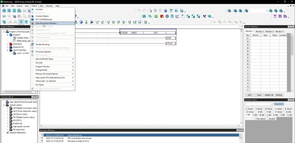
- Go to the Online tab
- Click “Link + Download + Monitor” to go online with your PLC.
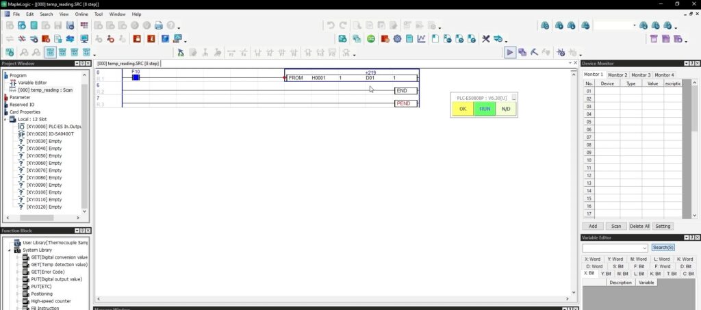
When online, you can see the live values from the Thermocouple Module
+219 in the application instruction reads as 21.9°C.
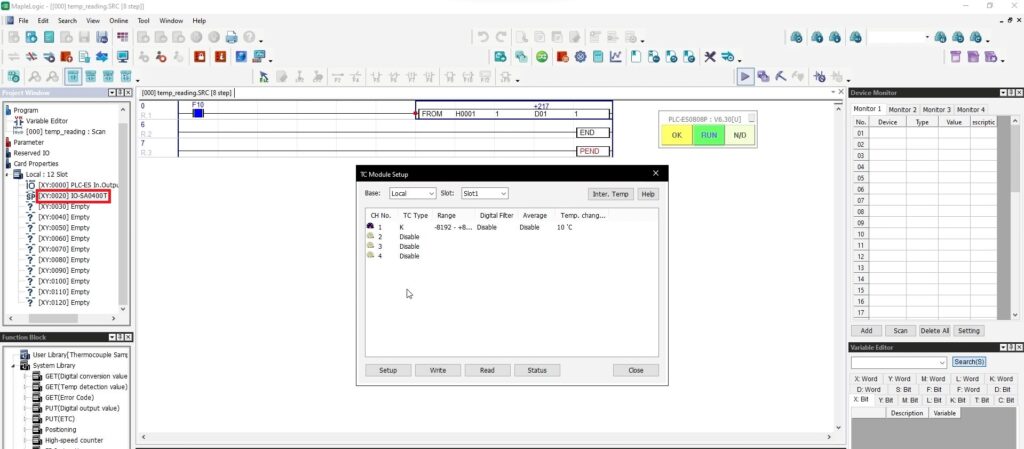
Over to the left side of your project, double click the Thermocouple Module to open the configuration window.
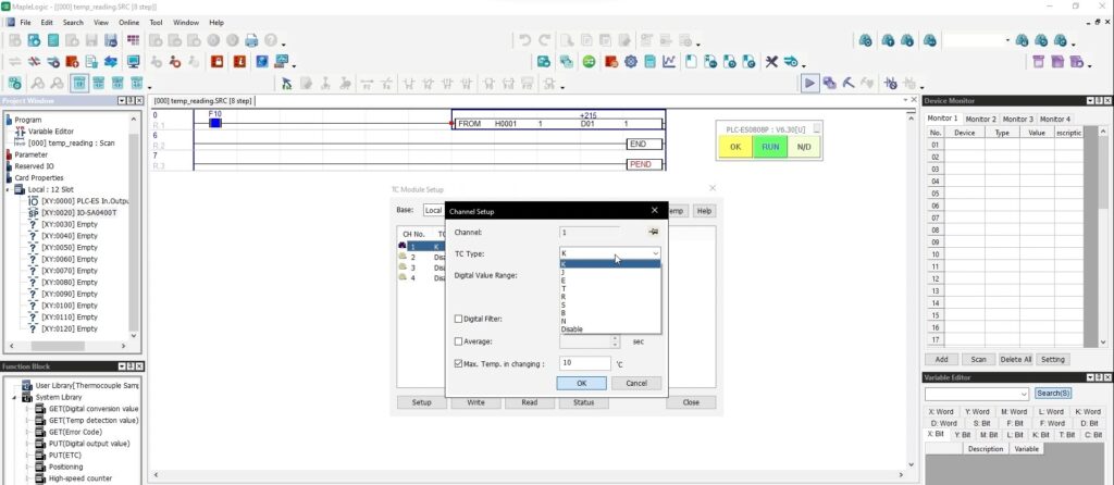
- Double click Channel 1
- Use the drop down menu to choose the thermocouple type.
- Click OK
After setting the configurations, you MUST click “Write” to save the settings to the PLC.
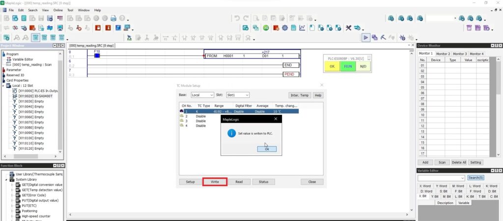
After writing to the PLC, click “Status” to view the live values from the Thermocouple Module.
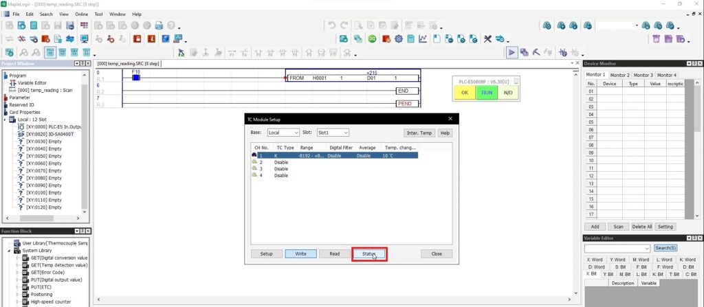
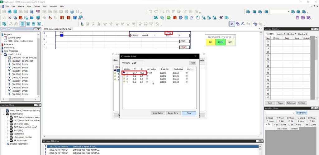
View the live values from the Thermocouple Module in the TC Module Status.
The Values should reflect in your ladder diagram.
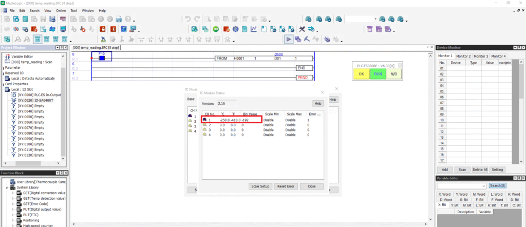
Thermocouple Error Status
There are several reasons why your Thermocouple Module can trigger an error code. A few could be a wire disconnection, exceeding the maximum and minimum temperature ranges or a power outage, to name a few.
Below is an example of a wire that’s disconnected. There are no values in the TC Module Status window.
Below you will see a live camera feed of the PLC and the Thermocouple Module connected to a K thermocouple.
One of the wires is disconnected resulting in a blinking error light on the Thermocouple Module.
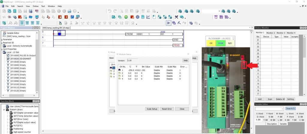
Re-connect the wire back into the Thermocouple Module.
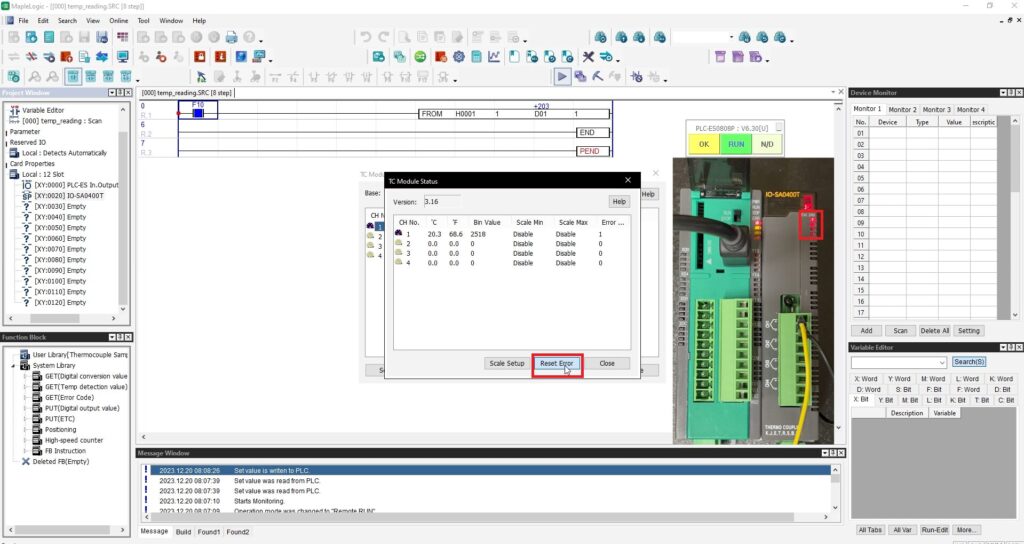
The values are now being seen in the program but the blinking error light won’t clear until the “Reset Error” button is pressed in the TC Module window in the program.
Click it and it will clear the error light.
Sample Project
The project shown above was designed for the specific hardware mentioned at the beginning of the tutorial and is intended to provide you guidance when programming your unit. If you are using models other than the ones specified in this sample project, similar steps can be duplicated within your own project.
Download MapleLogic Sample Project
Resources & Documentation
Maple PLC/MapleLogic Resources
More
Tutorials
Sample Projects
See our Support Center for a complete list of Quick Start and Installation Guides
About the Author
