This tutorial will cover how you would configure your I/O modules virtually in MapleLogic and converting them into ladder diagram without having the physical hardware.
Software Required
Hardware Required
- Maple Modular PLC’S – Any Maple Modular PLC can be used.
- Maple Micro PLC’S – Any Maple Micro PLC can be used.
Virtual I/O Configuration
- This method can be used if you DO NOT have the physical Maple Modular PLC and I/O modules and can be run in an offline simulation.
- For example: the configuration settings can be saved and sent to a customer or engineer. They can apply the same settings to their project and implement them to their Maple Modular PLC and I/O modules.
- To apply the configuration settings, simply switch from STOP to RUN mode on the PLC or in Maple Logic.
- To apply the same configuration settings that were created virtually to a physical Maple Modular and I/O modules, you MUST initially have the same I/O modules in the correct slot order when loading the project file. More I/O Modules can be added later on if needed.
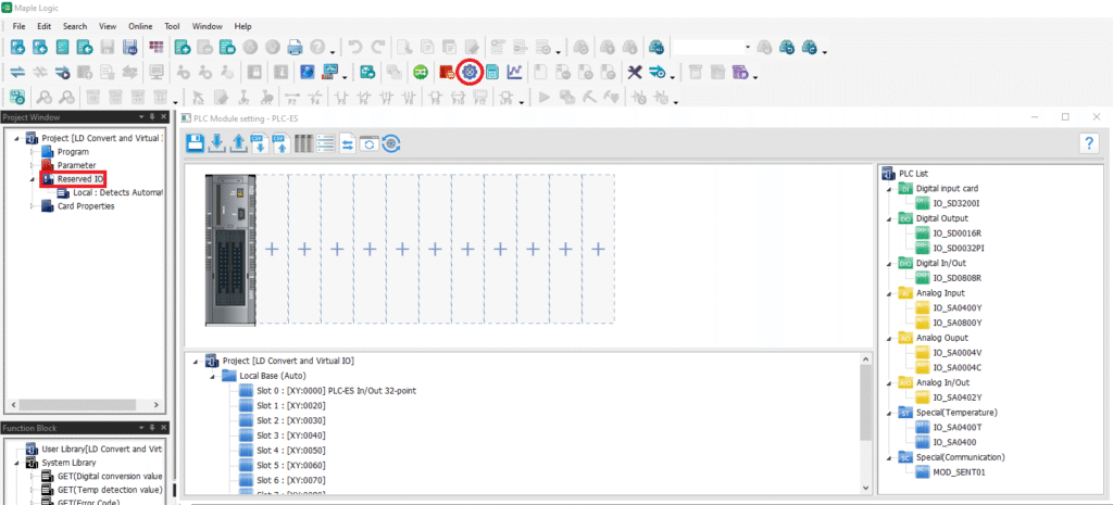
To configure the I/O modules virtually, either click the “I/O Reservation” button or double click the “Reserved I/O” on the left.
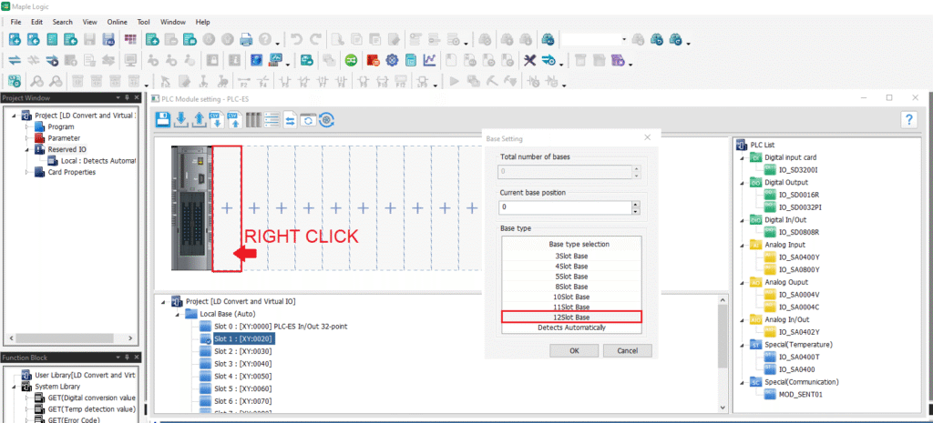
Right click on the slot space >> Select “Base Setting” >> Choose “12Slot Base”. You will need to select this to add up to 11 I/O Modules.
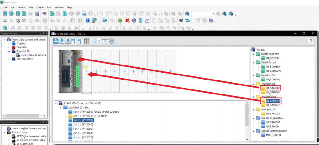
Drag the I/O Module from the right side to the appropriate slot number. Once the I/O module is placed, it will be displayed.
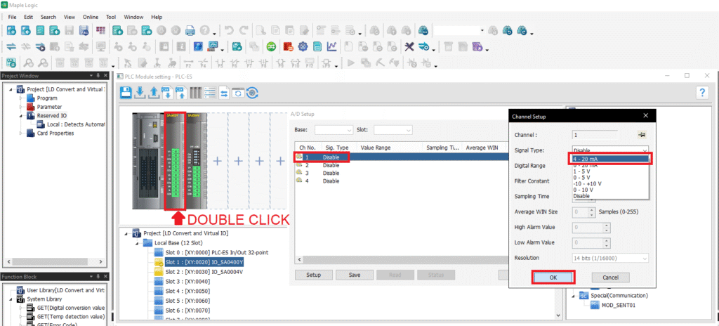
Double click on the I/O module >> Double click on the channel >> Choose the signal type >> Click OK.
Ladder Diagram Conversion
- Automatically converts all the I/O configuration settings into ladder diagram.
- This method should only be used if you DO NOT have the physical PLC and I/O Modules.
- This method is ONLY used for configuration purposes and not to send or receive real values from an I/O module.
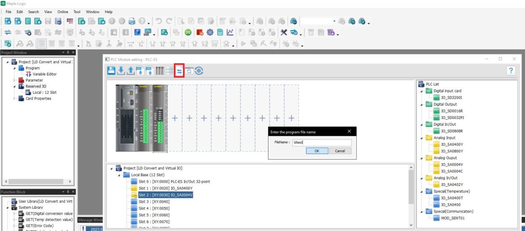
Click the “LD Conversion” button >> Name the program (must be 12 characters or less, no special characters, no spaces).
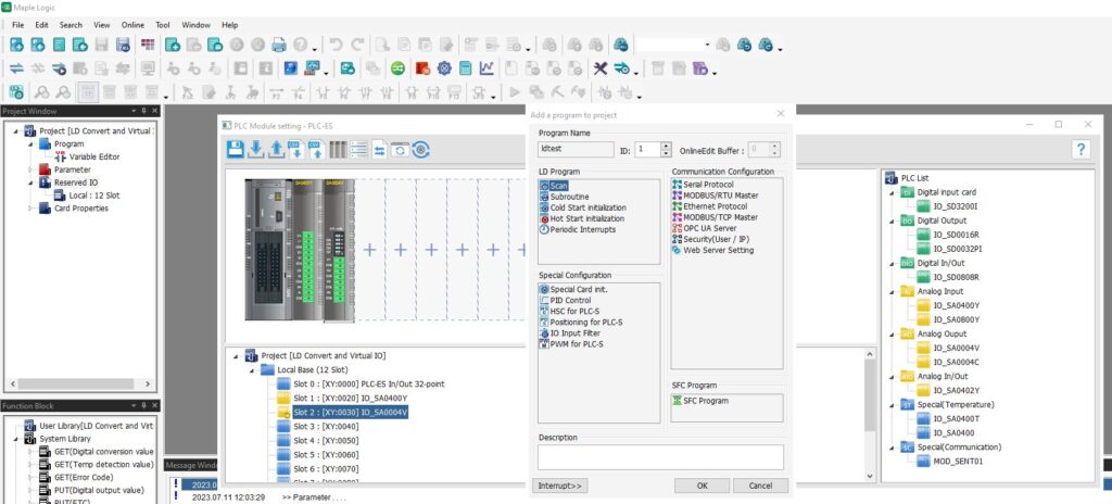
Next, it will add the LD conversion program as a scanned program into the project.
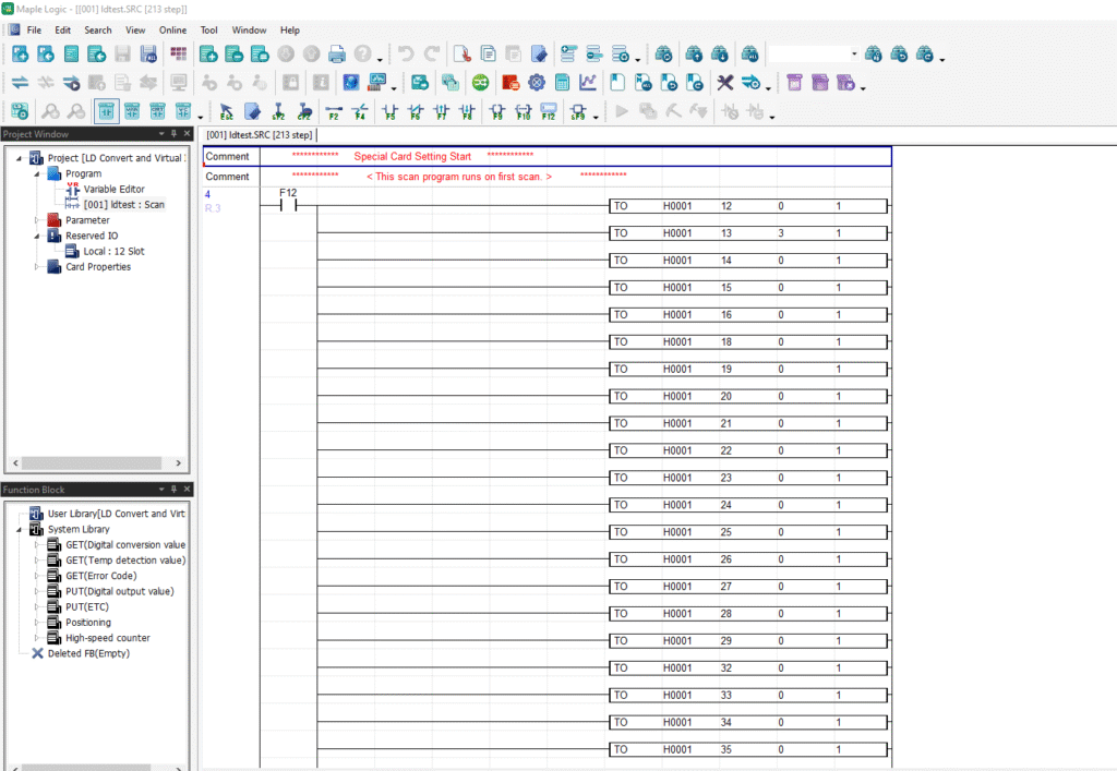
Sample Project
The project shown above was designed for the specific hardware mentioned at the beginning of the tutorial and is intended to provide you guidance when programming your unit. If you are using models other than the ones specified in this sample project, similar steps can be duplicated within your own project.
Download MapleLogic Sample Project
Resources & Documentation
Maple PLC/MapleLogic Resources
More Tutorials Sample Projects
See our Support Center for a complete list of Quick Start and Installation Guides
About the Author
Trusted source for industrial automation & control solutions
Follow Maple Systems:
