In this tutorial, you’ll learn how to set up and use Alarms and Syslog features to keep your network running smoothly and detect issues before they cause downtime. We’ll walk through how to configure Alarm DIP switches, view alarm details using the web interface, and enable Syslog logging to record important system events. By the end, you’ll understand how to monitor power failures, system alerts, and other critical events in real time—and how to make sure those alerts are logged, visible, and actionable across your network.
Software Required
MapleLink Lite User Interface (Enter the network switch’s IP address into a web browser to access its web interface.)
Hardware Required
- MS1-L05G01F
- MS1-L08G
- Embedded Industrial Box PC (A web browser is required. Use one of our Industrial Box PCs.)
Alarm Functions in Network Monitoring
In network management, alarms play a vital role in monitoring, detecting, and alerting administrators to network issues in real time. Alarms notify users of events such as power supply failures, link interruptions, port errors, or abnormal traffic levels, helping teams take quick action before downtime occurs. By configuring alarm settings on managed switches or network devices, IT staff can proactively identify and respond to system faults, improve uptime, and maintain reliable network performance. Alarms can be displayed through web interfaces, dashboards, or SCADA systems, and are often categorized by severity to ensure critical issues receive immediate attention.
Overall, alarms help network managers:
- Detect faults quickly before users or connected devices are affected.
- Isolate problems to specific equipment or ports.
- Automate responses, such as switching to redundant power or notifying maintenance staff.
- Maintain uptime and reliability across critical systems.
Alarm Configuration


Notice:
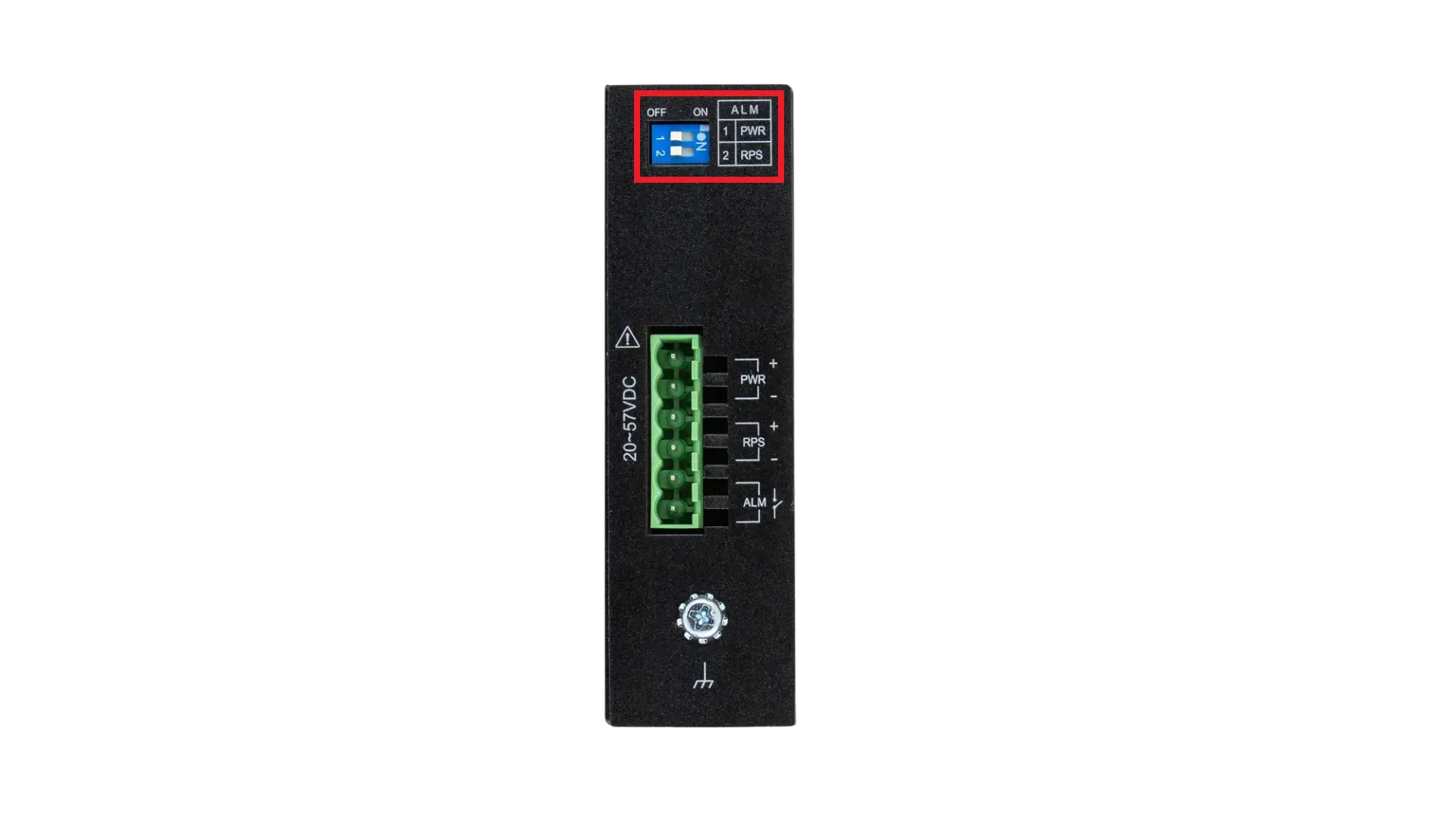
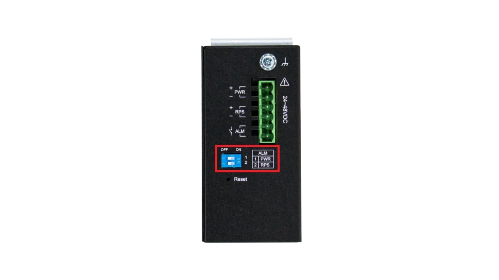
The Alarm DIP Switch allows users to configure whether an alarm message should be sent when specific events occur.
For example:
- PWR: ON – The switch will send an alarm message if the main power supply is disconnected.
- RPS: ON – The switch will send an alarm message if the redundant power supply is disconnected.
CLI Command
| Node | Command | Description |
| enable | show alarm-info | This command displays alarm information. |

Alarm Web Information
| Parameter | Description |
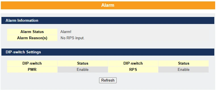
| Alarm Status | This field indicates if there is any alarm events. |
| Alarm Reason(s) | This field displays all of the detail alarm events. |
What is a Syslog?
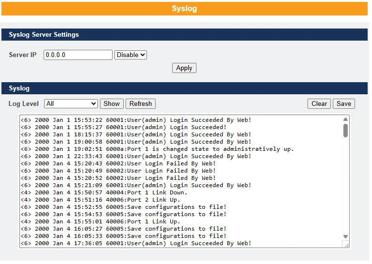
The syslog function records certain system information for debugging purposes. Each log message is recorded with one of the following levels: Alert, Critical, Error, Warning, Notice, or Information. The syslog function can be enabled or disabled; by default, it is disabled. Log messages are stored in the switch’s file system. If a syslog server IP address is configured, the switch will also send a copy of each log message to the syslog server.
The log file is limited to 2,000 entries. When the file is full, the oldest entry will be overwritten.
CLI Configuration
| Node | Command | Description |
| enable | show syslog | This command displays all log messages recorded in the Switch. |
| enable | show syslog level LEVEL | This command displays the log message with the LEVEL recorded in the Switch. |
| enable | show syslog server | This command displays the syslog server configurations. |
| configure | syslog-server (disable|enable) | This command disables / enables the syslog function. |
| configure | syslog-server ip IPADDR | This command configures the syslog server’s IP address. |
Example:
- L2SWITCH#configure terminal
- L2SWITCH(config)#syslog-server ip 192.168.200.106
- L2SWITCH(config)#syslog-server enable
Syslog Server Setting Web Configuration

| Parameter | Description |
| Server IP | Enter the Syslog server IP address. Select Enable to activate switch sent log message to Syslog server when any new log message occurred. |
| Apply | Click Apply to add/modify the settings. |
| Refresh | Click Refresh to begin configuring this screen afresh. |
| Log Level | Select Alert/Critical/Error/Warning/Notice/Information to choose which log message to want to see. |
| Clear | Click Clear to clear all of log message. |
| Save | Click Save to save all of log message into NV-RAM. |
Real-Life Scenario
Scenario: Water Treatment Plant — Critical Pump Power Monitoring

Setting
A municipal water treatment plant relies on several high-capacity pumps to move water between processing stages. These pumps are controlled by PLCs (Programmable Logic Controllers) and connected through an industrial managed switch with primary (PWR) and redundant (RPS) power supplies.
The switch is configured with Alarm DIP Switches and Syslog logging to catch power-related issues before they cause downtime.
The Problem
During normal operation, the primary power supply for the industrial switch controlling the intake pumps fails due to a breaker fault. If the redundant power supply fails before anyone notices, the PLCs controlling the pumps will lose communication, stopping the intake process and potentially disrupting water flow to the community.
How Alarms and Syslog Prevent Downtime
- Alarm DIP Switch Setup
- PWR: ON – Alarm triggers if the main power supply is disconnected.
- RPS: ON – Alarm triggers if the redundant supply is disconnected.
- Fault Detection
- The Alarm DIP Switch detects the main power supply failure.
- The industrial switch sends an alarm message to the plant’s SCADA system.
- SCADA shows a flashing red alert at the pump station and triggers an audible siren in the control room.
- Syslog Function
- Syslog is enabled and logs the power failure both locally and to the plant’s central Syslog server.
- The event is recorded with a Critical severity level.
- The Syslog server automatically sends the log to the maintenance management system, creating a high-priority work order.
- Maintenance Response
- The maintenance team receives an instant mobile notification about the power fault.
- A technician replaces the faulty breaker while the pumps continue running on redundant power.
- Normal operation is restored without any service interruption.
Outcome
- No downtime in water pumping operations.
- All power events are logged for regulatory compliance.
- The alarm and syslog integration ensures immediate detection, logging, and escalation of critical issues.
Resources & Documentation
Lite-Managed Network Switches Resources:
- Industrial Network Switches
- Industrial Lite-Managed Network Switches – MS1 Series Datasheet
- MS1-L05G01F Quick Start Guide
- MS1-L08G Quick Start Guide
- What is a network switch?
- Industrial Network Switch Operations Manual – Lite-Managed Series
More
Tutorials
Sample Projects
Software Downloads
See our Support Center for a complete list of Quick Start and Installation Guides
About the Author
Trusted source for industrial automation & control solutions
Follow Maple Systems:
