Upgrade OIT5400A from 8K to 32K RAM
Technical Note 1055
Applicable Model(s)
OIT5400A
Title
Upgrade OIT5400A from 8K to 32K RAM
Date
10/23/2023
Rev
00
P/N
0907-1055

Static Precautions

Do not attempt to proceed with the installation of the Maple Systems 32K Static RAM unless you have a STATIC-FREE work station. PERMANENT DAMAGE may occur to electronic devices being handled because of an ESD event. Eliminate the chance of a destructive ESD event by taking the following precautions:
- Discharge personal static by grounding yourself prior to handling the Maple OIT5400 and the
SRAM. - Only handle the OIT5400 and SRAM at a properly-maintained STATIC-FREE work station.
- Connect chassis of the OIT to a clean ground before handling it any further or installing the
SRAM. - After the rear cover has been removed from the OIT5400, place the unit in an anti-static bag
during any transport.
Removal of 8K SRAM
1.
Disconnect the OIT5400 from power before inserting or removing the SRAM.
2.
Take the rear cover off the OIT by removing the 2 Sems screws. Set cover aside.
3.
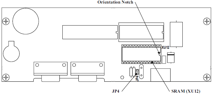
Locate the 8K SRAM. It is on the main PCB just below the Flash PROM. The Flash
PROM has a label on it: 7531-0097. The 8K SRAM is a 28-pin chip labeled on the PCB as
XU12. It has a part identifier number with 6264 in the number that identifies it as an 8K
SRAM. See Figure 1.

4.
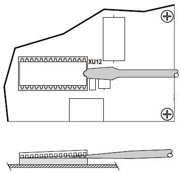
Insert a standard size blade screwdriver under the end of the 8K SRAM as shown in Figure 2. Gently pry up just a little, then move the screwdriver a little further in, prying up a little more as you go.
Repeat the gentle prying motions while carefully moving the screwdriver towards the opposite end of the SRAM.

Installation of 32K SRAM
1.
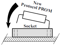
Locate the orientation notch in the 32K SRAM as shown in Figure 1. Then line up one row of pins in the socket while tilting the 32K SRAM as shown in Figure 3.

2.
Align the second row of pins by applying a sideways pressure on the SRAM.
3.
Push the SRAM straight down in the socket until fully seated. Check to be sure no pins have been bent.
Installation of Jumper
1.
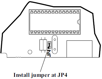
Locate jumper JP4 which is directly below the SRAM on the main PCB, see Figure 4. Solder a short piece of 24 gauge wire to jumper the JP4 connection.

