Networking HMIs with RS-485
Technical Note 5030
Applicable Model(s)
All Models
Title
Networking HMIs with RS-485
Date
7/29/2015
Rev
01
P/N
0907-5030
Summary
This technical note covers basic wiring principles that should be followed when installing multiple HMIs in an RS485 network configuration. Employing these principles will help the controls engineer to create a trouble-free installation.
Control systems often require operator input from a number of different locations in the system. Since it is not cost effective to run a separate communications line from the host to each terminal location, a local network is desirable when multiple terminals are needed. With the Maple Systems touchscreens this can be achieved through a multidrop RS-485 network.
RS-485 networks allow multiple devices (up to 32) to communicate at half-duplex on a single twisted-pair of wires plus a signal ground wire; or full-duplex using two twisted-pairs of wires plus a signal ground wire. The maximum communications distance can be up to 1200 meters (4000 feet). By adding repeaters, this length can be extended. A repeater can ‘refresh’ a weak signal and drive another 4000 feet.
Solution
Note Long networks are especially vulnerable to improper impedance, grounding and surge problems. Most problems can be addressed by isolating the nodes. Use optically isolated repeaters and isolated converters to attach the individual nodes of the network to create reliable long-distance solutions.
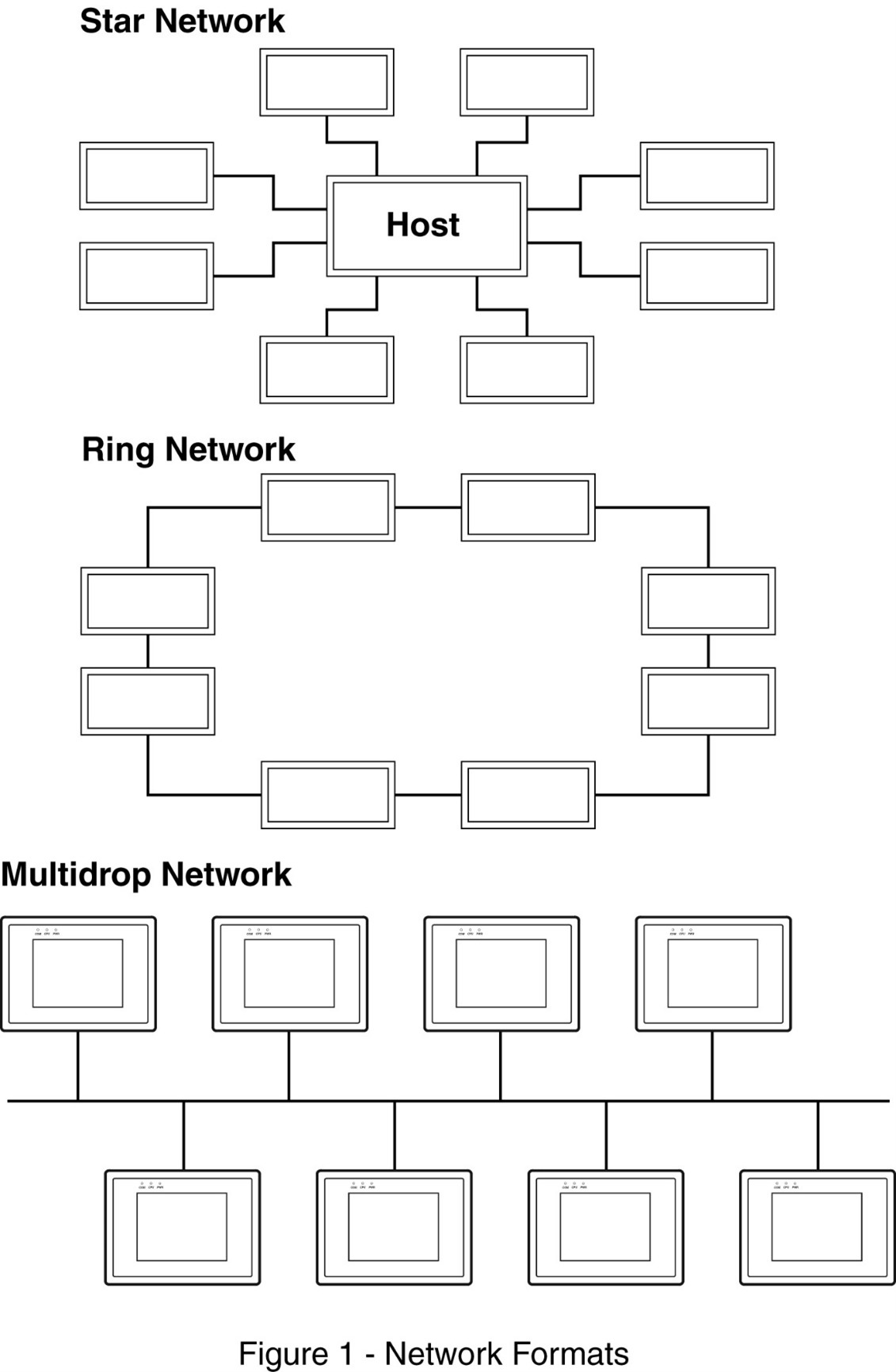
There are several different forms of RS-485 communications networks. The main formats are the ‘star’, ‘ring’, and ‘multidrop’ networks (see Figure 1). Each has its own set of advantages and disadvantages. Since the HMI touch screens only support the multidrop format of network, this is the one that will be further discussed.
RS-485 Multidrop Network
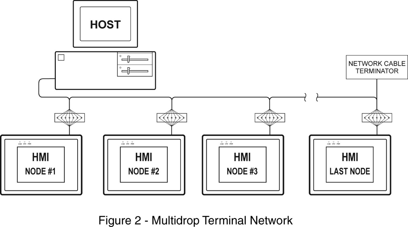
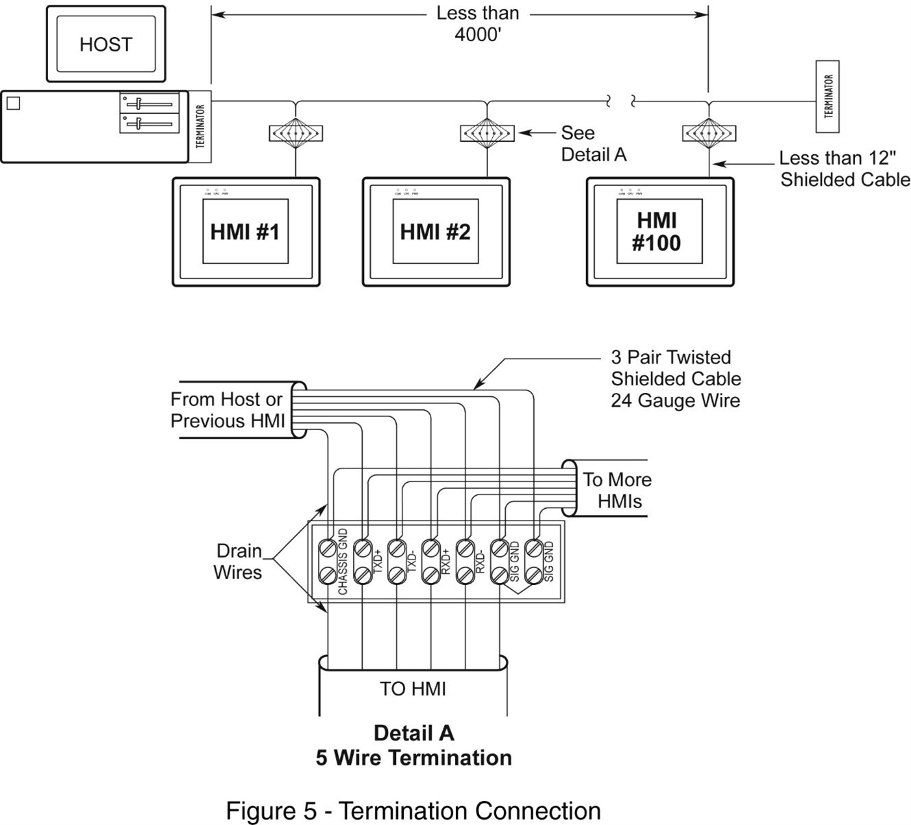
The RS-485 multidrop network consists of a host or master HMI (located at one of the network ends) connected to multiple PLCs or HMIs (nodes) via a single, continuous 4-wire data link. Typically, each node is connected to the network by locally tapping into the data link with short T-OFF (or stub) cables. In a T-OFF, each node “taps off” the main line with a short stub cable. This stub cable should be as short as possible to reduce line reflections. We recommend a distance of less than 12” for each stub cable. A terminal block is used at the point at which the stub cable separates from the main cable to facilitate connections between nodes.
Since the network is controlled by a single host controller, each end of the data link must be properly terminated to reduce transmission-line reflections and interference. The total length of the data link, from the host to the end terminator, can be up to 4,000 feet long. The number of nodes that can be connected to the network is 32 or less, depending upon the transceiver loading, data rate (baud rate), and over-all cable capacitance. Network repeaters can be added to the data link if needed, allowing additional nodes to be connected for each repeater used (up to a maximum of 127 nodes).
Communications Wiring
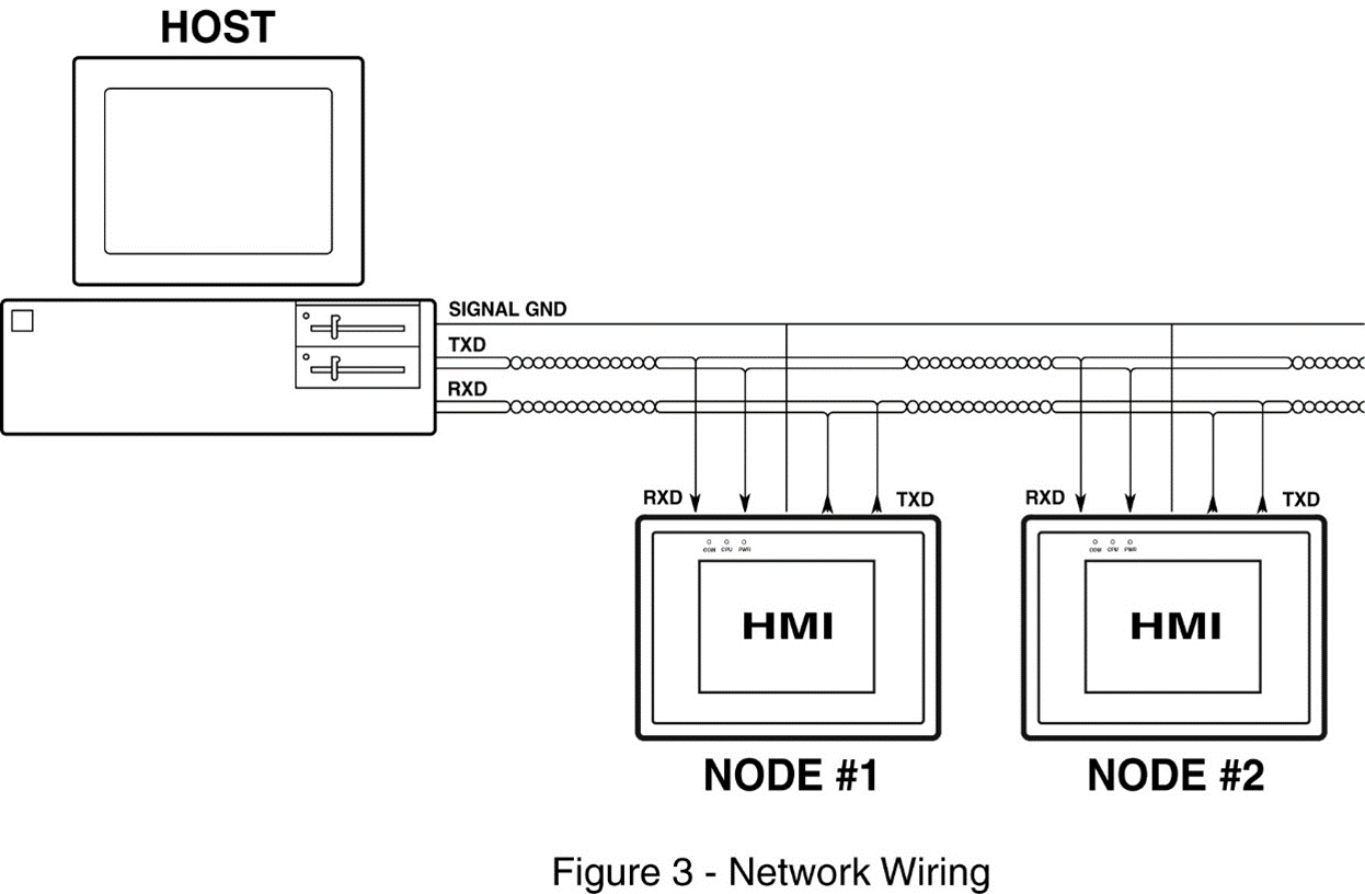
The 4-wire network data link consists of two twisted pair sets of conductors and a signal ground. One of the twisted pair is connected to the host transmit lines (TX+ & TX-) to the entire network node receive lines (RX+ & RX-). The other twisted pair has the entire node transmit lines connected together and going into the host receive lines. The single wire is used as a communications signal ground. For short networks (under 1,000 feet), low-capacitance 28-gauge wire such as BELDEN #9805 or BELDEN #8133 may be used. For longer networks (over 1,000 feet) 24-gauge wire such as BELDEN #9843 or BELDEN #8333 should be used. Each of these Belden cables consists of 3 sets of twisted pairs, so the signal ground is connected to one of the twisted pairs instead of a single wire.
Network Termination
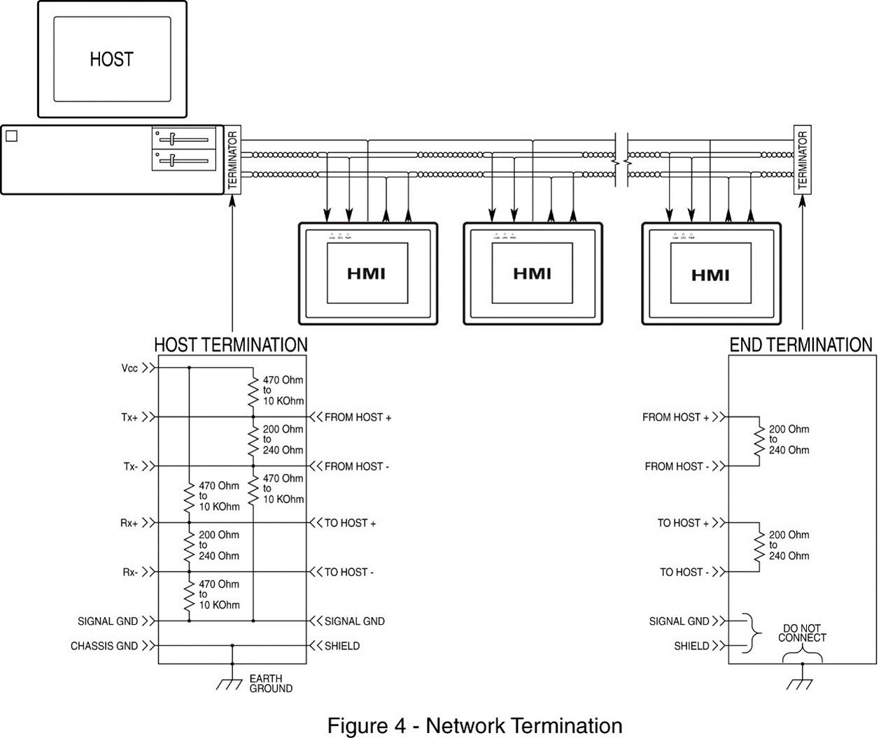
Proper network termination matches the impedance of a node (transmitter/receiver) to the impedance of the transmission line (cable). When impedances are mismatched, the transmitted signal is not completely absorbed by the load and a portion reflects back into the line.
The network data link must be properly terminated to reduce the amount of signal bounce and noise pickup from the surrounding environment. The terminating resistor must match the characteristic line impedance of the cable, which is generally around 120 ohms. This is accomplished by using termination resistors at both ends of the network cable. The value of the termination resistor must roughly match the characteristic impedance of the cable. This will allow the full signal to develop at the resistor — which has no capacitance or inductance of its own — preventing any signal reflection from occurring on the line. Figure 4 shows a typical termination circuit. The host termination shown is only needed if the host’s RS-485 adapter does not contain any built-in terminator circuitry. The end termination must be done at the extreme end of the network cable. If the network cable ends at the last installed node, the end termination can be connected using that node’s terminal block.
Terminal Connection
Each of the nodes is connected to the network data link using a T-OFF terminal block connector. In this instance, each of the network wires are cut, stripped, and reconnected using the T-OFF terminal block screws to capture each cable lead (see Figure 5). The network cables shields must be connected together to maintain shield continuity. The maximum length from a T-OFF terminal block and the node RS-485 communications connector should be no more than 12 inches.
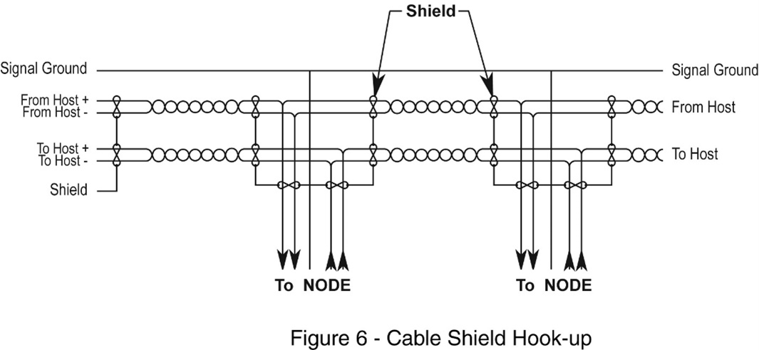
As shown in Figure 5, each node “taps off” the main line with a short stub cable. This stub cable should be as short as possible to reduce line reflections. We recommend a distance of less than 12” for each stub cable. A terminal block is used at the point at which the stub cable separates from the main cable to facilitate connections between nodes. Note that the shield wire is also connected to the terminal block in order to maintain connection between cables for maximum protection against noise. For proper shielding, all of the cable shields should be connected together with the shield wire connected to an earth/chassis ground point at the host end. Each stub cable should have its shield wire connected to the node’s chassis ground pin.
Network Grounding
To communicate properly, serious attention must be paid to the grounding scheme of any device connected to the network data link. Improper grounding, termination, and faulty shielding of the data link is one of the most common causes of system failure in a multidrop network. For proper operation, the following general rules must be observed:
1.
The cable shield must not be used as the signal ground.
If attempting to try and reduce the cost of the cabling by using a 4-wire cable with the shield used as the signal ground, DON’T DO IT. The initial cost savings are always exceeded by the maintenance costs once the system is operating under field conditions. Often, it is necessary to completely replace the network data link with the proper cable (5- wire plus shield) to eliminate noise problems in the system.
2.
The cable shield should be connected to the chassis ground only at one point. This should be at the host connection for the best noise immunity.
The cable shield is often connected to the chassis ground at both ends of the cable connection. Since this makes an earth ground to earth ground connection between the two devices, it can cause what is called a “ground loop” problem. Since the earth grounds are probably at different voltage potentials, a large current (often several amps in magnitude) will flow between the earth ground points. The shield usually has lower impedance to the current flow than the normal earth ground current path. This can result in the cable shield carrying large amounts of unexpected current. For proper shielding to be accomplished, all of the cable shields should be connected together in a contiguous whole, and then grounded only at a single point (at the host chassis ground).
3.
The signal ground must not be connected to the chassis or earth ground.
The chassis ground is intended as a safety ground for power supplies, EMI filters, voltage spike protection circuits, 120 VAC neutral returns, and all manner of AC and DC driven devices. As a result, the chassis ground can carry large voltage potentials and currents. Connecting the signal ground to the chassis ground can damage the device connected to the network data link.
Other Considerations
The most common error when installing the network is running power lines (especially 110 VAC) in the same wire channel as the network data link. This is often done to reduce the cost of the wire conduit. Including a 110 VAC, 60 Hz line in the wire channel is sure to cause a loss of communications on a regular basis. If the AC line is powering relays, motors, or even fluorescent lighting, the high voltage spikes and noise WILL BE induced on the network data link, destroying any or all attached network devices. 208 VAC three-phase power is even worse since the voltage spikes and noise is of greater magnitude and intensity.
Short runs of low voltage DC power (+24VDC) can normally be included in a communications wiring channel or cable. This would allow a node to use a central power supply to power individual nodes by running the DC power lines with the network communications lines. However, DC power should not be run down the whole length of the network to power every device. Small clusters of nodes that are physically adjacent may be powered from a single supply if necessary.
Obtain the correct cabling. Transmission line losses consist of AC losses (skin effect), DC conductor loss, leakage, and AC losses in the dielectric. In high-quality cable, conductor and dielectric losses are approximately equal. Polyethylene cables offer much lower attenuation than PVC cables.
Avoiding Pitfalls: The best approach is preventative; determine the device communications characteristics before the system design is complete – ask the following questions during system design:
- Is this device configured for 2-wire or 4-wire systems?
- Is a signal ground connection available?
- Is the device isolated? Does it include any surge suppression devices?
- What value bias resistors, if any, are used in the device – and are they accessible for modification?
- Is the device terminated – and is this accessible for modification?
- What is the device response time (“turnaround delay”)?
- What is the programmable address range of the device?
- What baud rate or range of baud rates are supported?
More Information
For more information regarding communications and connection requirements, please refer to the operator manual and installation guides for the individual node units. This documentation can be found on the Maple Systems Web site: maplesystems.com.
For more information regarding RS485 networking and for a source of products for converting, isolating, and repeating RS-485 signals, Maple Systems recommends the B&B Electronics: www.bb-elec.com
