CODESYS
SoftPLC Software
CODESYS provides a control solution that is one of the most complete implementations of the IEC 61131-3 standard for PLC software on the market.
Combine the power of CODESYS with one of our CODESYS capable HMIs and Modular IO to create an innovative control solution that can tackle the most demanding applications. This unique architecture saves time, hardware cost, communication cabling, and valuable control cabinet real estate, without compromising on the CPU resources real time applications require.
CODESYS stands for Controller Development System and can be used for simple, or very complex, automation projects. As your project grows in complexity, CODESYS is capable of accomplishing many of those more sophisticated tasks, all within the CODESYS software platform instead of requiring multiple 3rd party applications or custom code that your engineers may spend weeks perfecting.
Features and Benefits
- Everything is integrated in a single user interface
- Complete IEC 61131-3 programming system – from classic PLC programming to object-oriented controller programming
- Extensive features for convenient project engineering and commissioning of automation applications, such as data monitoring, scanning for application errors (debugging), and changing the application during operation (online change)
- Optional add-on modules for methodical application development: UML®, version management, static code analysis, profiling, and test automation
- Configuration and commissioning of the most important industrial fieldbus systems or manufacturer-specific I/O systems
- Seamless integration of optional add-on components for project engineering: Visualization, motion control / CNC / robotics, safety modules
- Installation, maintenance, and training required only for a single user interface: Minimization of engineering effort
- Extendable function range through additional products available in the online store and with on-board tools (programming of function or communication libraries in the IEC 61131-3 languages, for example)
- Easy connection to a convenient Industry 4.0 platform for managing control landscapes per cloud
IEC 61131.3 Overview
IEC 61131-3 is a section of an International Electro-Technical Committee (IEC) standard that provides a definition for implementing PLC programming software. The standard was first introduced in 1993 as the result of an effort to standardize the myriad PLC logic editors in the automation market place. The goal of the standard is to give automation professionals a familiar environment and set of tools to create PLC programs across vendor platforms. CODESYS has standard IEC instructions and function blocks with editors implemented for all five programming languages defined by the standard:
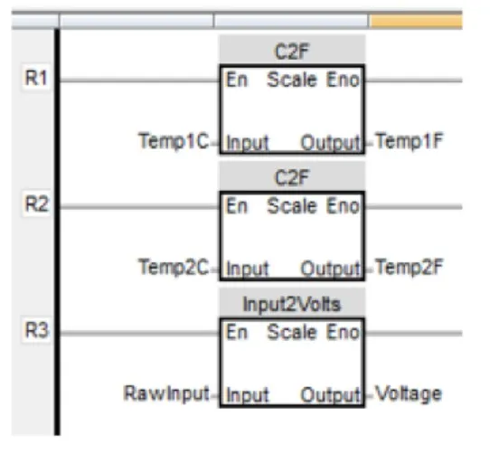
Ladder Diagram (LD) Editor
The Ladder Diagram editor uses the same programming paradigm as the Native Ladder editor. It is a graphic editor in which instructions are placed in a pseudo electro mechanical circuit. Instructions are activated by connecting them to the power rail of the circuit. Boolean operators are modeled as relay contacts and coils. Contacts can be arranged to block or allow power to flow from the power rail to downstream instructions based on the needs of the application. Coil instructions are activated when the circuit is on a logical state that allows power to flow to them.
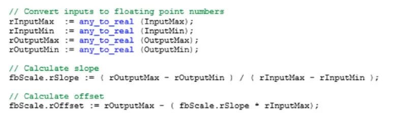
Structured Text (ST) Editor
The Structured Text editor is a text based editor similar to text based programming languages such as C/C++ or Visual Basic. Logical operations are created by combining variable names with operators to create logical statements. The PLC executes the statements from top to bottom as the program is executed. The Structured Text editor provides a great deal of flexibility to the programmer.
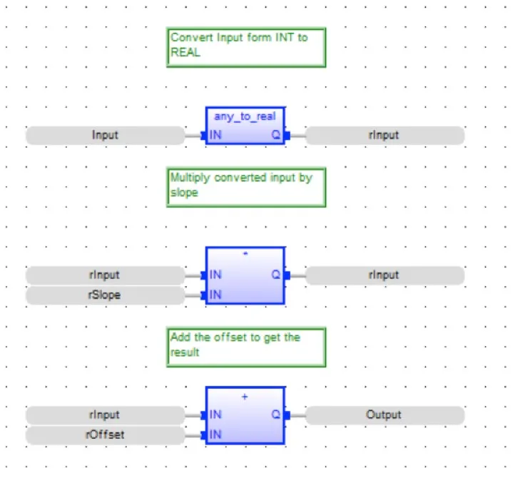
Function Block Diagram (FBD) Editor
Function Block Diagram is another graphical logic editor which is based upon logic diagrams. The program is constructed out of individual blocks that represent some operation, which will have one or more inputs and produce one or more outputs. Complicated logical operations can be constructed by interconnecting multiple blocks together.
Sequential Function Chart (SFC) Editor
The Sequential Function Chart is a state diagram that allows complex algorithms to be executed using a series of “steps” and “transitions”. Graphical steps are used to represent stable states, and transitions describe the conditions and events that lead to a change of state. Using SFC highly simplifies the programming of sequential operations as it removes the need to create multiple variables and tests just for maintaining the program context. However, SFC should not be used to create a decision diagram.
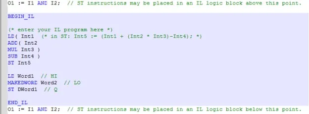
Instruction List (IL) Editor
Instruction List (IL) programming is the most basic of the five IEC 61131-3 programming languages. The format consists of a series of simple text statements. Each statement performs only one function. When creating an IL logic block, you must put all IL commands in between the BEGIN_IL and END_IL sections. Above and below this block, you are allowed to use ST instructions.
All IEC language editors include instructions and function blocks for:
- Scaling
- Data Transfers
- Mathematical Operations
- Comparisons
- Data Conversions
- Timers
- Counters
- PID
- Strings
- and more
User Defined Function Blocks (UDFB)
User Defined Function Blocks are a way of making the logic in a PLC program re-usable. The UDFB associates a set of inputs, outputs, and internal data with a logic sequence. Multiple instances of the UDFB can then be created and used throughout a program. Each instance of the UDFB will have its own set of data registers to work with. By using multiple instances of the same logic sequence, it is possible to make a change throughout a project by changing a single logic sequence in one place. UDFBs can also be used across different projects.

Get started with CODESYS today
A battle tested and complete PLC software package backed by a large userbase and development team, CODESYS fully implements the IEC 61131-3 specification. Implement your application in the programming language / editor of your choice. Use advanced object-oriented concepts to manage complex systems, and much more.
Case Studies
Read real-world applications. These case studies and success stories illustrate how our customers use our products to reduce costs, provide features, increase functionality, and solve problems.


Supervisory Control and Data Acquisition (SCADA)
Early on, these types of systems were built using proprietary hardware and software, operating in isolation without connections to other networks. operators had to reside in a centralized control room or command center because human-machine interfaces (HMIs) did not support remote access. Any information provided to personnel other than operators was delivered via reports, which often had a significant time lag. Once devices were connected to much larger networks, they became more complex and gained broad capabilities.
To learn more about how our products work together to create scalable SCADA solutions, visit our SCADA solutions page