Position instructions are commands used in motion control systems to define specific movements mechanical components will follow.
In this guide, we focus on how PLC’s utilize position instructions to precisely adjust the positioning of a machine component, such as a stepper motor, to move on a specific path. In addition, you’ll learn how to implement position instructions into your own system by following our demo project utilizing an HMI, a PLC, and a stepper motor. For more general information, please read our previous article covering stepper and servo motors.
1. Position Instructions Overview
Position instructions define specific movements that mechanical components should make in motion control systems. These components can include stepper motors and/or servo motors – used in robotics to pick up and place objects at desired locations, or in CNC machines to remove material by following designated paths.
By initiating data instructions, machines move to precise locations in a controlled and accurate manner. Applications that use position instructions increase productivity and reduce potential errors by ensuring precise control over movement. This consistency helps mechanical components follow predefined paths accurately every time.
Position instruction provide control over position and speed at each step along a predefined path. The following aspects can be adjusted between steps:
- Path planning: Ensure the path is feasible within the environment and avoid obstacles that could affect the desired positioning.
- Speeds: Determine safe operating speeds and the acceleration/deceleration for each movement.
- Feedback: Select a mechanism, if needed, to verify whether the positioning is accurate
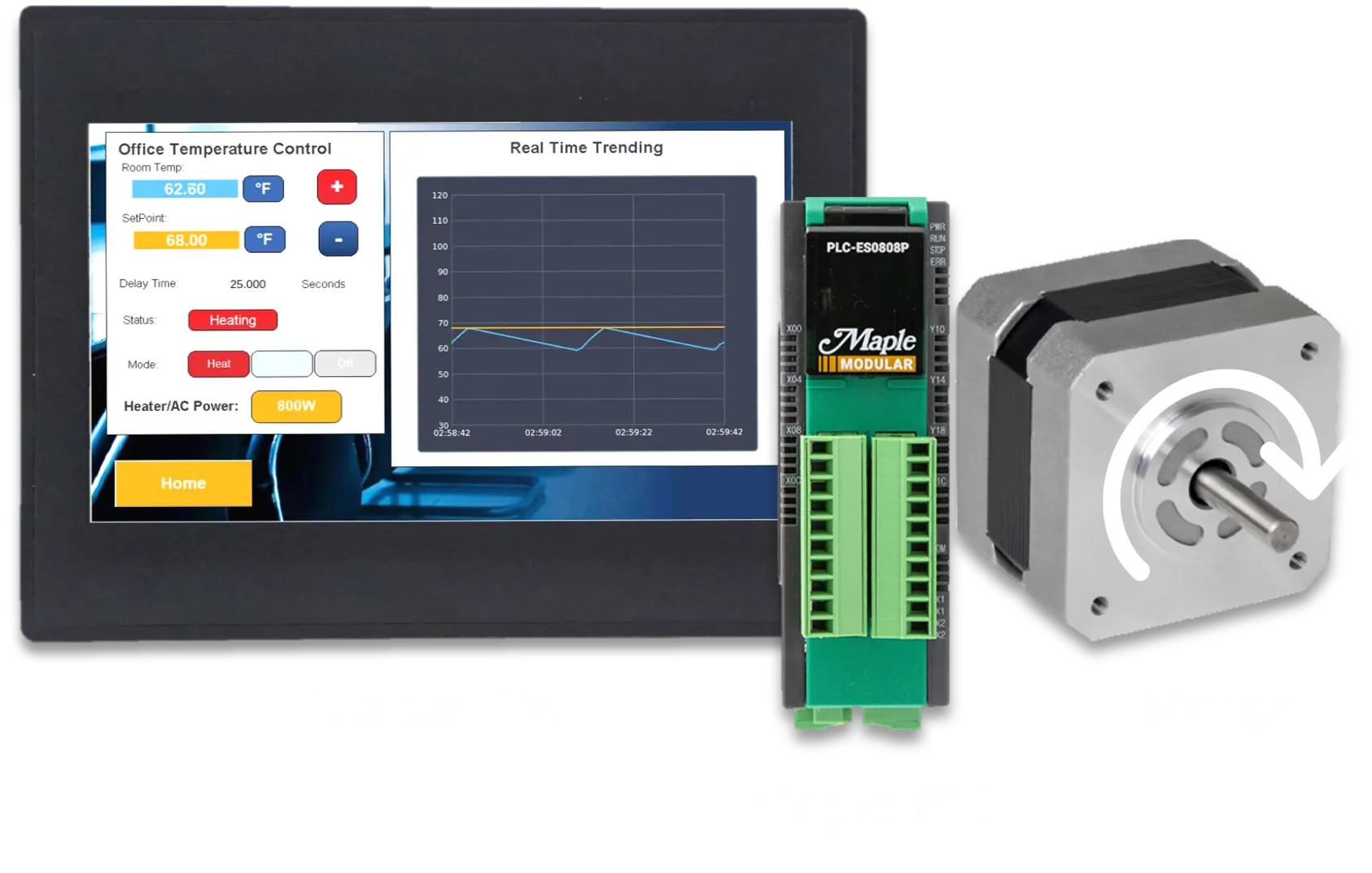
For this example, we’ll use a Maple HMI, a Maple PLC, a motor driver, and a stepper motor to build a simple motor positioning demo. This project includes visual elements, basic programming, and a general positioning control design.

The position instruction portion of our demo application will utilize a single momentary button on the HMI to initiate the position data predefined in our PLC program. Using an HMI is not required for position instructions, however, it is a great way to visualize motor status and control PLC operations without physical buttons being wired to the PLC.
2. Maple Systems PLCs
Before we go further into the programming of position instructions, we will revisit the physical digital inputs and outputs used in positioning and how the PLC controls which signals are sent to the motor.

You can use digintal input pins to easily implement upper and lower limits for each axis by connecting them to physical sensors. Additional digital inputs are also availiable for Origin Point Return (OPR) control, which can be triggered using the position instruction commande. However, we’ll cover this feature in a later article.
Whether you’re using a Modular PLC or the Micro, there are four digital output pins that send PTO signals to control up to two axes. Two of these pins (Y10 and Y12) send pulse signals to control how many steps the motor takes. The other two pins (Y11 and Y13) determine the direction in which the motor rotates.
Below, you can see how the Maple Systems PLC sends positioning signals for the X-axis.

The PLC sends pulse signals through the first digital output (Y10) and sends the logic output signal through the second output (Y11). In simple terms, Y10 tells the driver how many steps the motor should take, and Y11 determines the direction the motor will turn.
When you set Y11 to ON, the motor driver sends Clockwise (CW) positioning instructions along with the pulse signals. When Y11 is OFF, the driver sends Counterclockwise (CCW) positioning instructions instead.
Note: Maple PLCs supports two-axis position control. However, for simplicity, we will program only one axis in this article. For more details, refer to the positioning control manual.
3. Positioning Instructions Configuration
Before creating the application lets go over how to configure the positioning instructions. When creating a new position program there are a few tabs that will be used; first the specific axis parameter tab and the position data tab.
Axis Parameters
The axis position tab allows you to set the basic, extended, and OPR parameters of your position program. For simple position instruction, not including OPR, we only need to configure the bias speed at start, speed Limit value, and acceleration/deceleration times.

Position Data
The position data tabs allow you to configure up to 30 position data for each axis. You can access these settings by clicking the “Position Data” tab for the desired axis.
Each step can have a different control function – including position, speed, and loop control – as well as its own acceleration/deceleration times, operational speeds, and more. The carious control functions and how to program position data are explained in the MapleLogic Position Instructions section below.
In the example below, we’ve created 5 position data entries under the “X-axis Position Data” tab. Each data number lets users define the control pattern (continuous or single-step control), acceleration and deceleration times, control method, dwell time, operation speed, and target position address.

For each position data users can configure:
Below is a table showcasing all control system codes and their functions:

For more detailed information on the parameters please refer to section 1.7 in the positioning user manual.
Additionally the Operation Data Table and Monitor Window tables covered in the Manual Positioning article are great tools to monitor positioning statuses such as current step, speed, and position of the application.
4. MapleLogic Positioning Instructions
In MapleLogic Position Instructions are used to execute three different operations; position data, OPR control, and high speed OPR control. To execute position instruction in logic we’ll use the PSTRT instruction and fill in the required parameters shown below:

| n | Axis Number (X=1, Y=2) |
| n1 | Slot Number (CPU = 0 [H0]) |
| n2 | Position Data Number 1-30: Position Data Number 9001: OPR 9002: High Speed OPR |
| n3 | Result Flag |
Position Data Instruction
Uses the position data configured in the X or Y Position Data tabs. As shown below

As an example, using the x-axis position data from table 4, when Y105 is turned ON position control from No.1 to No.5 will be performed. The D250 register will show any errors that have occurred.

OPR Control Instruction
Uses the OPR parameters set in X or Y axis parameter tab to control origin point return control. These settings will allow users to carry out positioning to return to the origin point utilizing the PLC’s digital inputs listed in the table below.

As an example, using the X-axis parameter data from figure 5, when X100 is turned ON OPR control is enabled.

For an in-depth description of the OPR methods available on the Maple PLC see section 1.5.12 in the position user manual, and for a positioning example using OPR control see section 1.11.3.
High Speed OPR Control Instruction
High Speed OPR uses the same parameters as the normal OPR control, however, when operating will not use the OPR low speed parameter when reaching the origin point. Below is an example of enabling high speed OPR control using the X-axis parameter data from figure 5.

When X0 is turned ON, high speed OPR control is enabled.
After all configuration changes are made, we can layout which Modbus addresses are used to control the motor. Below is the table of Modbus addresses we will use to control the stepper motor
5. Download Software
Next, we will need to do is download our respective product software’s, EBPro for our HMI and MapleLogic for our PLC. Below are links to the direct download of each software:


After you have installed both software programs, we can start configuring and programming our demo application. The HMI and PLC programs used in this demo project can be downloaded at the bottom of the page.
Below is the Modbus Mapping table we will use for our demo motor control project.

6. PLC Project
We are almost there! Below is simple scan program, using ladder logic, to control the positioning of the stepper. As you can see we only utilize a few contacts, timers for delays, set bits, and reset bits to control the motor.
Position Instructions are predefined in the position data window of the position program, shown below.

This may seem daunting, but it’s actually very simple. In the first step, we set the current position address (POS) to 0. In the second step, we move the motor to an absolute (ABS) position of 4000 steps. The third step increments (INC) forward by another 2000 steps, and the fourth step does the same, incrementing forward by another 2000 steps, and a fourth step does the same, incrementing forward by another 2000 steps. Finally, the last step returns the motor to an absolute (ABS) position of -4000.
For more details on control systems and parameters, refer to the position manual.
To enable position control, we’ll use the PSTRTn instruction below:

The position instruction starts with the first step in the position data and runs until step 5, where continuous control ends.
It’s always important to add logic to safely stop operations. The first stop command we use is the deceleration stop command (D0.1) which gradually stops the operation to avoid abrupt halts.

The second command we will use is the emergency stop request (D0.2) which will stop all operation immediately without and deceleration.

7. HMI Project
The HMI project only requires one momentary button to trigger the position instruction process.
For help with setup, refer to the previous positioning article and video tutorial. These resources walk you through how to establish communication between the HMI and PLC, and how to create various control and monitoring objects in the HMI software (EBPro).
After you’ve successfully established communication, create one momentary buttong to initiate the position fdata instruction using Modbus Address 0x166.

You can do this in EBPro by creating a “Set Bit” button object. Specify the device you want to connect to, choose the Modbus address 0x1666, and select “Momentary” as the button attribute – just like we did earlier when creating the JOG Forward button.

Expanding on this, we can create a complete HMI project that can control all Modbus registers listed in Table 5.
8. Running the Applications
The last few steps are to wire up all devices, supply power, and download the respective projects to your HMI and PLC. Then run your applications!
In the above demonstration, the position data instruction is shown from 0:31 to 0:46
PLC and HMI Sample Projects:
This downloadable file has all the necessary projects to recreate and run the positioning demo project described in this article.
9. Video Tutorials
Read and watch our additional positioning tutorials to learn how Maple Systems built-in positioning programs operate.

Introduction to Stepper Motor and Servo Motor Positioning
This article covers the basics of positioning and speed control of a motor utilizing a Maple PLC and a Maple HMI for visualization. Learn how to use built-in positioning special programs.

Manual Positioning with Maple Systems PLCs
This article covers the basics of manual positioning utilizing a Maple PLC and a Maple HMI. Learn how to use JOG forward and backward using manual position commands.

Position Control with Maple System’s PLCs
This article covers the basics of positioning and speed control of a motor utilizing a Maple PLC and a Maple HMI for visualization. Learn how to use built-in positioning special programs.

How to Set Up Maple PLC and Maple HMI using Modbus RTU and TCP Communications
This tutorial will cover Modbus Communication via RTU and TCP between a Maple PLC and a Maple HMI. The PLC as a Slave device and the HMI as the master device.
Resources and Information
Sample Projects
We have created sample applications/projects and sample kits that demonstrate software features, give programming information for specific controllers, or demonstrate product capabilities.
Additional Resources
Download software, manuals, guides, sample projects, controller information sheets, cable drawings, CAD drawings, tech notes, or watch a tutorial video to get you started in our Support Center.
SCADA Systems
Maple Systems offers all the components to create own unique level of supervisory data acquisition control, from the simplest stand-alone machine to sophisticated multi-device networked production line(s) all the way to enterprise-level operations.
About the Author
Trusted source for industrial automation & control solutions
Follow Maple Systems:
Share: