This tutorial shows you how to turn a 24V DC motor output on and off with an HMI+PLC combo by using Pulse Width Modulation (PWM). It also shows how to display the motor control data on the user interface.
In the example below, you will review the required hardware, wiring layout, software logic, and user interface used to control the motor output.
Software Required
Hardware Required
- HMC4070A-M — Other HMC2000 and HMC4000 models can also be used.
- HMC3-M1212P0200 V2 — Other HMC3 V2 I/O modules can also be used.
- 24 VDC Power Supply (4010-0011)
- 24V DC Motor — Other DC motors can also be used. This motor is shown only as an example.
Wiring and Circuit Design

You can also use this wiring diagram with other HMC3 V2 I/O modules that support digital output.
Digital Output DC Motor Wiring
- Power Supply:
- Red wire: 24V power supply to 24V on I/O
- Black wire: 0V power supply to 0V on I/O
- Digital Output:
- Red wire: Y0 24V to motor
- Black wire: 0V ground to motor
Software Code
This section walks through the programming logic used to control the 24V DC motor with PWM. First, we’ll review the ladder diagram implementation. Then, we’ll look at a Structured Text example that shows another IEC language option for handling the same type of control.
Ladder Diagram
The ladder diagram below shows the PWM logic used to control the 24V DC motor.

Structured Text
You can also use Structured Text as another IEC programming language option.
IF Slot01_CH1_Pulse_EnableFlag THEN

RAMPUpDown ( DutyInput, AccelerationSpeed, DecelerationSpeed, TimeChange, Reset ) ;

DutyOutput := RAMPUpDown.OUT;

END_IF;

IF Slot01_CH1_Pulse_EnableFlag THEN

Slot01_CH1_ON_DutyOrMaxFreqSettingReg := any_to_udint ( DutyOutput ) ;

END_IF;
User Interface
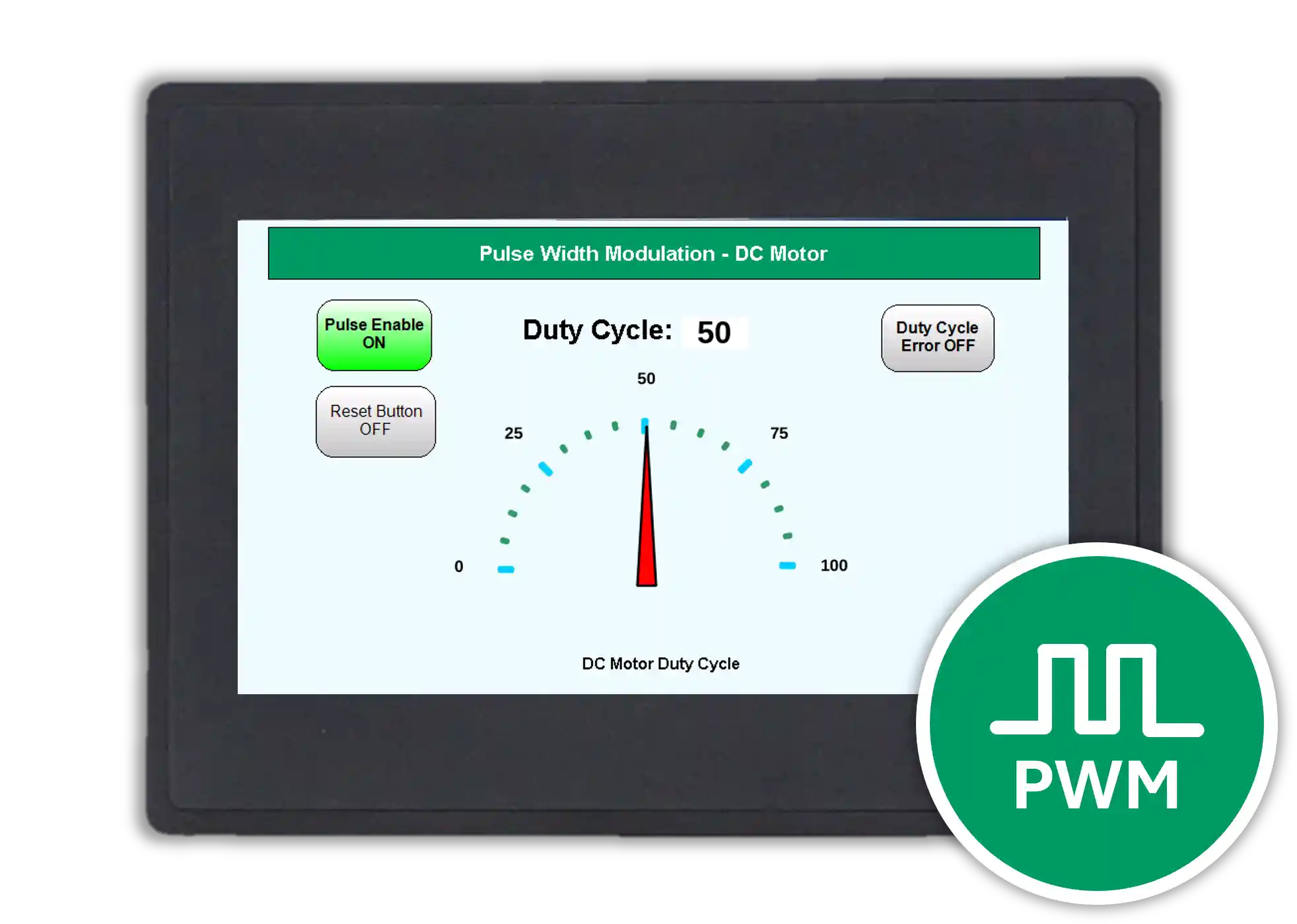
The user interface below shows the PWM motor control example on the HMI+PLC combo.

Final Thoughts
Using PWM to control a 24V DC motor with an HMI+PLC combo gives you flexible digital output control and a clear visual interface for monitoring operation. By combining the wiring example, ladder logic, Structured Text example, and user interface shown in this tutorial, you can build a practical motor control reference for your own project.
If you are using different compatible hardware, you can still follow the same general approach and adapt the example to your own application requirements.
Sample Project
The project shown above targets the specific hardware listed at the beginning of the tutorial and provides guidance when programming your unit. If you use different models than those specified in this MAPware sample project, you can follow the same steps within your own project.
Resources & Documentation
The following guides and documentation are specific to the hardware used in this integration tutorial and will help you with setup, configuration, and programming:
- MAPware-7000 Getting Started Guide
- MAPware-7000 Programming Manual
- IEC 61131-3 Programming Guide for MAPware-7000
- HMC3 I/O Module Guide
Looking for additional learning resources? Explore our library of tutorials, example projects, and software tools to help you get the most out of your system:
Also, browse our Support Center for a complete list of installation guides, FAQs, and additional technical documentation.
About the Author
Trusted source for industrial automation & control solutions
Follow Maple Systems:
Share:


