A PLC in an MQTT environment connects real-time machine control with modern industrial data systems. In packaging facilities, PLCs manage cycle counts, rejects, run status, and active fault conditions. The PLC executes control logic locally while publishing production data to a central MQTT broker. Instead of constant polling, the PLC pushes updates only when values change, improving efficiency.

Once the data reaches the MQTT broker, it can be instantly distributed to multiple subscribers such as a SCADA system, cloud dashboard, or analytics platform. This publish/subscribe model allows operations personnel to gain real-time visibility into production performance, downtime events, and machine health without complex drivers or custom integrations. Because systems subscribe to data rather than request it directly from the PLC, additional dashboards or software platforms can be added later without modifying the PLC program, making the architecture scalable and flexible.

The image above is an MQTT dashboard illustrated to show a machine monitoring interface focused on both production metrics and communication health. A bar chart compares product counts across eight machines, with Machine 1 leading at approximately 9,200 units and Machine 5 trailing at around 2,100 units. A green MQTT status indicator and “No Errors” message confirm a healthy broker connection. Below, each machine displays its ON status along with individual product counts and uptime and downtime values, providing clear, real-time operational insight.
Software Required
- Any PLC software can be used (MapleLogic used in this example)
- EBPro (Required software for the cMT-G01X – IIoT Communication Protocol Gateway)
Hardware Required
- Any PLC can be used (A Maple Systems PLC is being used in this example)
- IIoT Communication Gateways (The cMT-G01X – IIoT Communication Protocol Gateway is being used in this exmaple)
- any MQTT Broker (I’ll be using a local Mosquitto MQTT server on a PC as an example).
- (Optionally) an MQTT client software (I’ll be using MQTT Explorer for this tutorial).
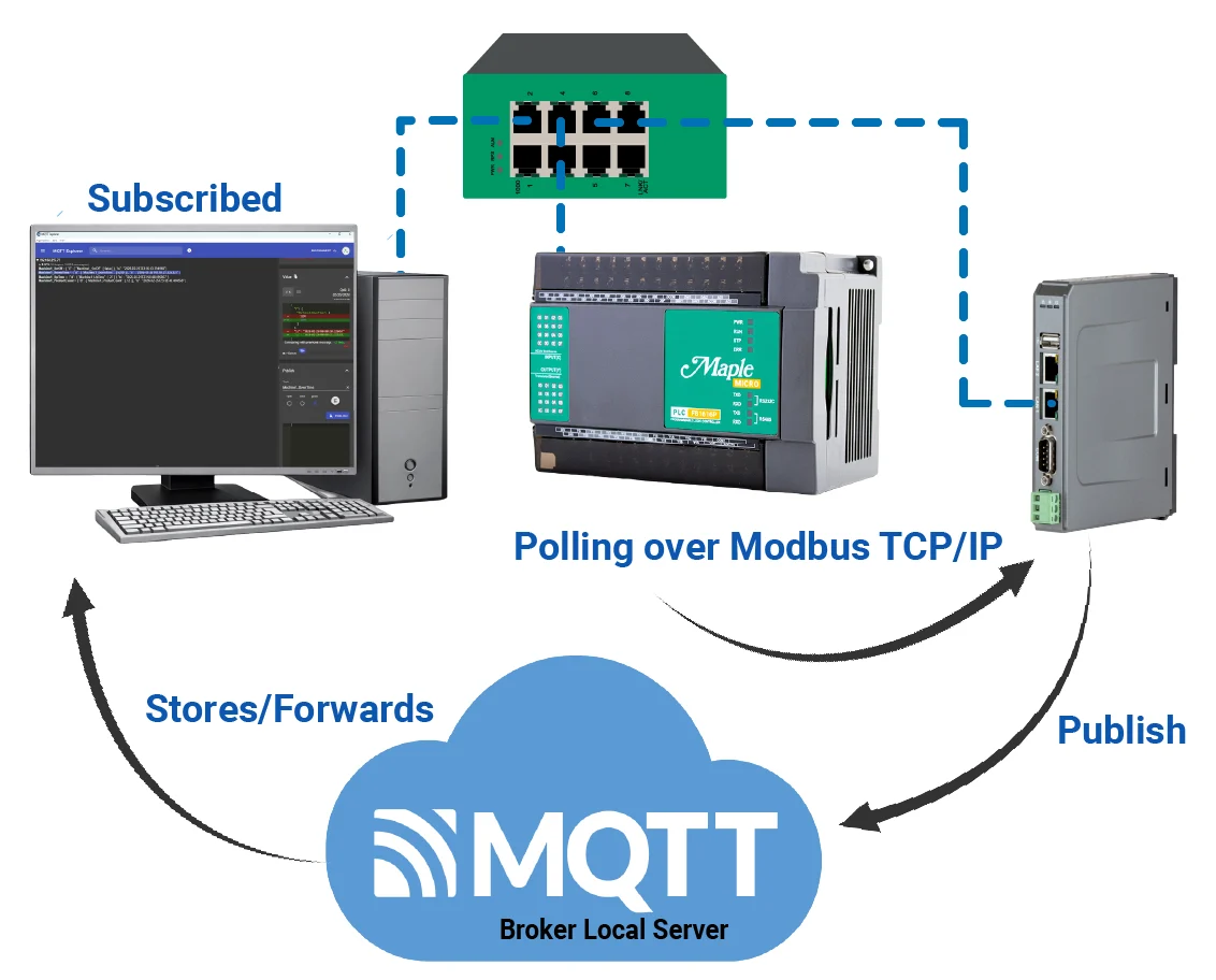
Network Diagram

Above is the network mapping used in this article. This diagram shows a local industrial network where a PLC, a Gateway HMI, and a PC are connected through a network switch on the 192.168.255.x subnet.
The PLC (192.168.255.76) communicates with the Gateway HMI (192.168.255.108) using Modbus TCP/IP, with the HMI polling the PLC for data. The Gateway HMI acts as an MQTT client in publisher mode, sending the collected PLC data to a local MQTT broker server.
The broker then stores and forwards the messages to subscribed clients. A PC (192.168.255.75) running MQTT Explorer functions as an MQTT subscriber, receiving and displaying the published data.
PLC Configuration
This section will walk you through the intial setup of a new project in MapleLogic using a Micro PLC (FB1616P0202).
Initial Setup in MapleLogic
Follow this step by step guide for getting started with a new project in MapleLogic.
Instructions: Initial Setup in MapleLogic
Start a New Project in MapleLogic
– For this example, select the PLC-FB
– Click Next to continue to next step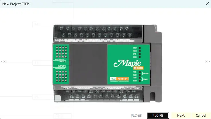
Set Project Details
– Choose the CPU Type: PLC-FB1616
– Name the Project
– Click OK to continue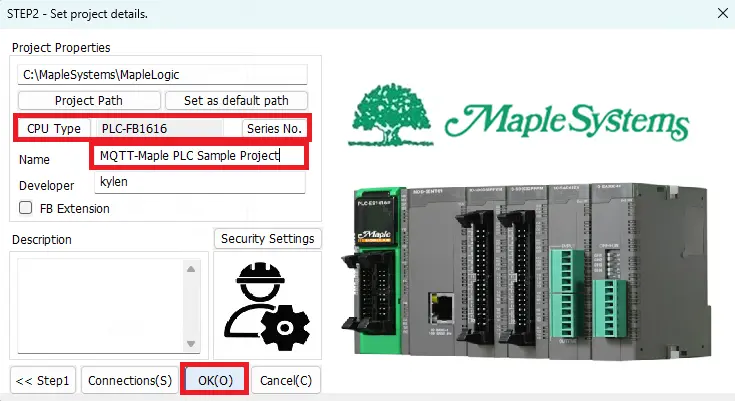
Start a New Scanned Program
– Right click on Program
– Select Scan under LD program
– Name the program
– Click OK to continue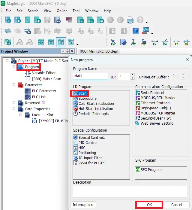
PLC Parameter Settings
– Double click on PLC Parameter
– Select the Ethernet tab
– Enter the IP address
– Click OK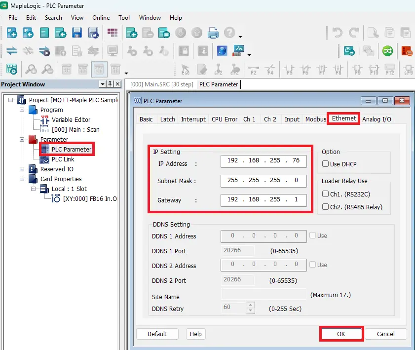
Modbus Addressing
– Here is where to view the modbus settings
– In this example we’ll be using a Coil Status Register (Y) which is a 0x address.
– Holding Registers (D) will be used as well which are 4x addresses.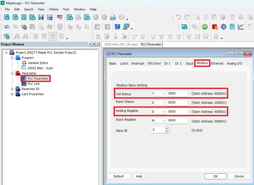
PLC Logic Build
This section will walk you through the ladder logic build needed for a simple MQTT communication scenario including a machine on and off bit, machine up time, machine down time, and machine product count. If you need to learn more about MapleLogic please refer to the MapleLogic User Manual. We also have over two dozen MapleLogic Tutorials on our website.
MQTT Ladder Logic Project Build in MapleLogic
Follow this step by step guide for creating the ladder logic in MapleLogic.
Instructions: MQTT Ladder Logic Project Build in MapleLogic
PLC Ladder Logic Layout
– Here is the logic that’ll be used in this example.
– 4 rungs of logic for turning Machine 1 on and off, product count, up time, and down time.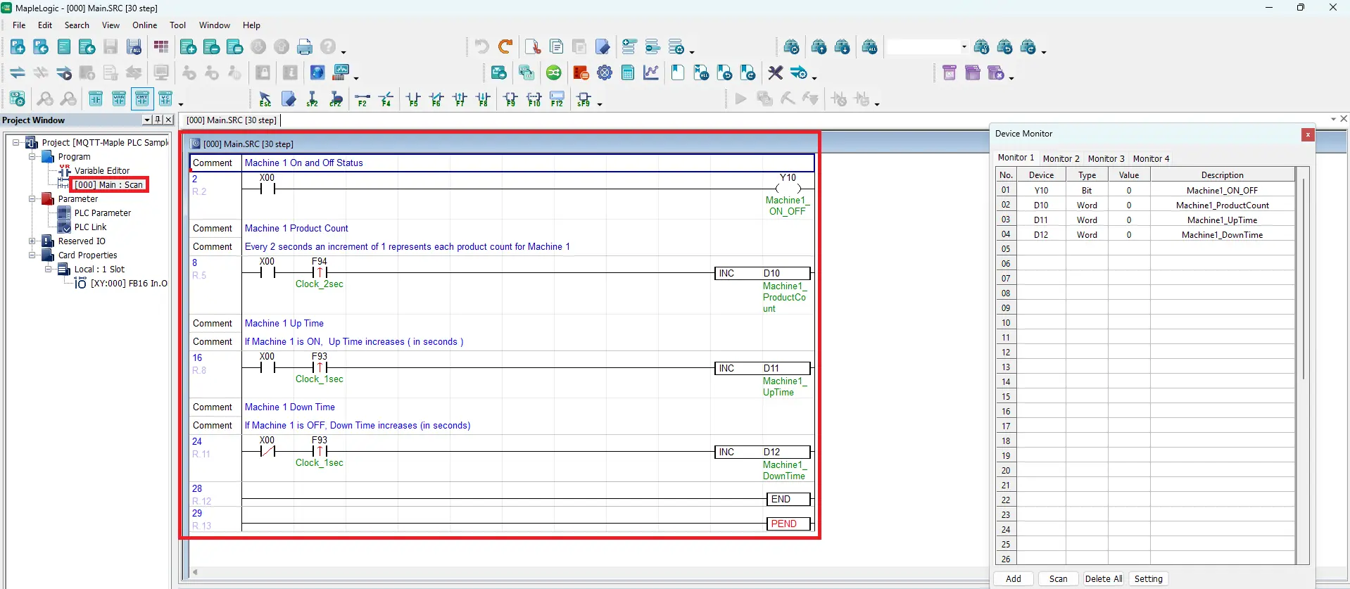
Machine 1 On and Off
– Add a Normally Open Contact (F5) on rung 1. Use X00 as an external contact.
– Use Y10 as the Machine1_ON_OFF Coil (F9)
– You can view the device registers in the Device Monitor window on the right side.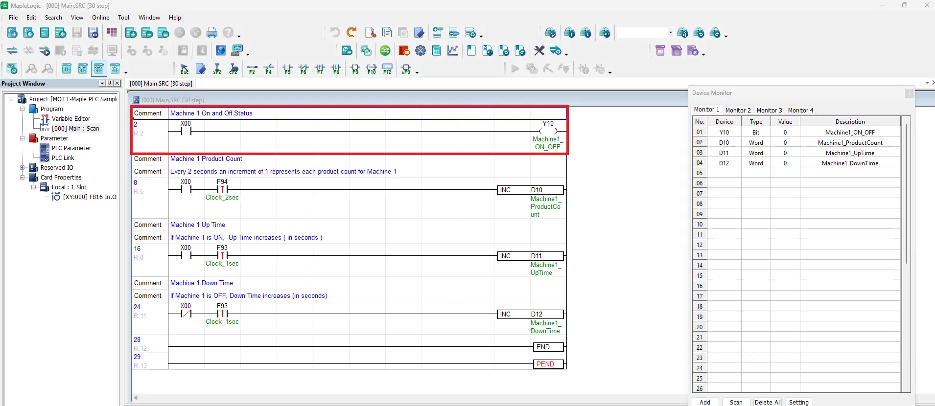
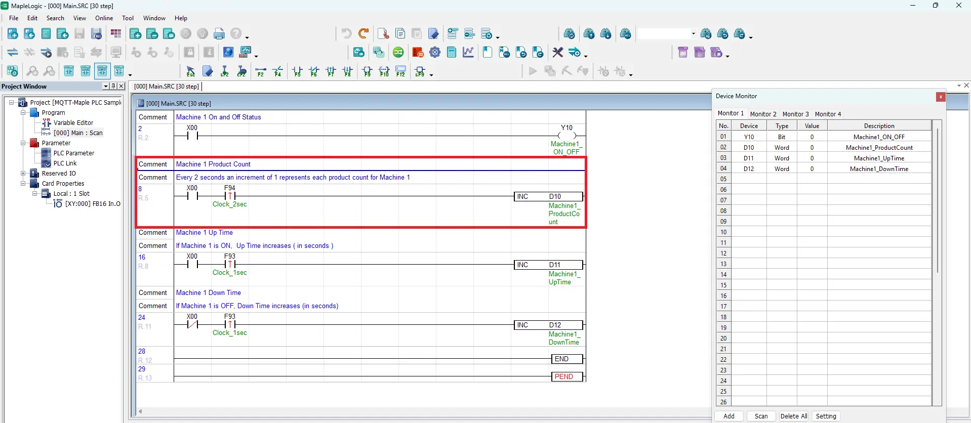
Machine 1 Product Count
Add a Normally Open Contact (F5), use X00. Add a Positive Transition – Sensing Contact (F7), use F94 for a 2 second clock timer. Add an Application Instruction, use an increment instruction to be stored in a 16-word register D10. Name it Machine1_ProductCount
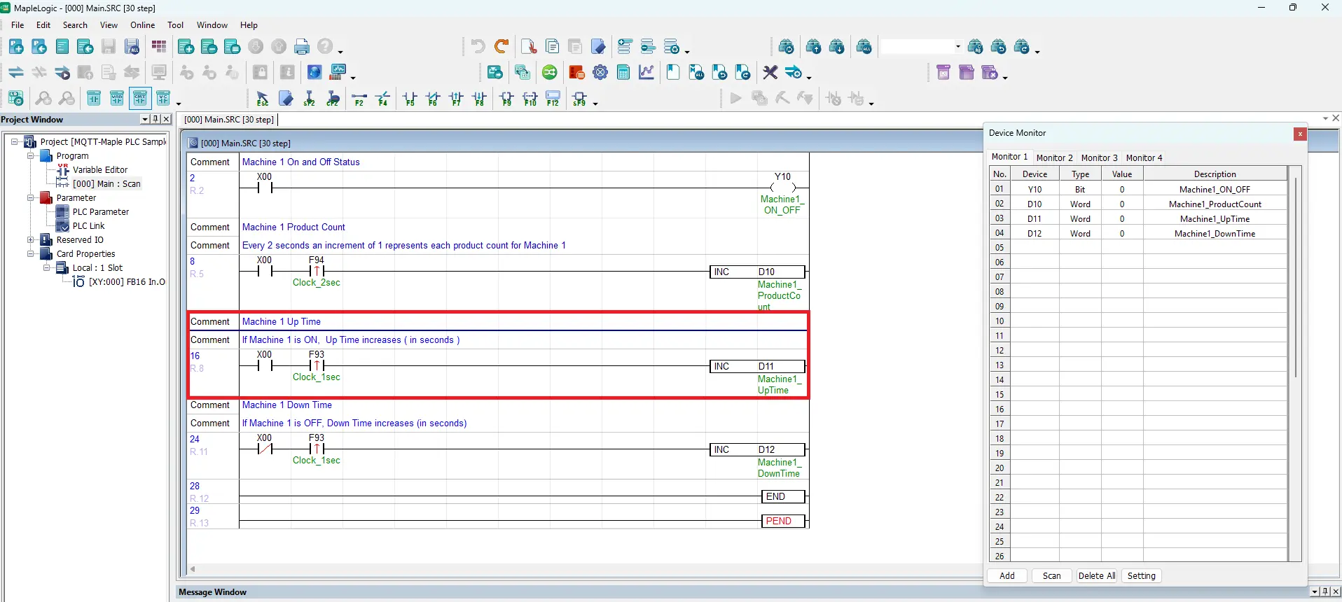
Machine 1 Up Time
Add a Normally Open Contact (F5), use X00. Add a Positive Transition – Sensing Contact (F7), use F93 for a 1 second clock timer. Add an Application Instruction, use an increment instruction to be stored in a 16-word register D11. Name it Machine1_UpTime
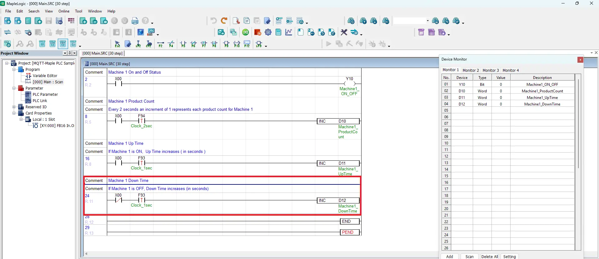
Machine 1 Down Time
Add a Normally Closed Contact (F6), use X00. Add a Positive Transition – Sensing Contact (F7), use F93 for a 1 second clock timer. Add an Application Instruction, use an increment instruction to be stored in a 16-word register D12. Name it Machine1_DownTime
Variable Editor – Y Register Modbus Address
– Navigate to View > Variable Editor
– Select Y: Bit
– Here is where to view the modbus address for Y10. It’s 000017 or 0x_17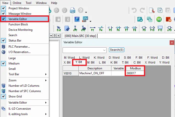
Variable Editor – D Word Modbus Addresses
– Navigate to View > Variable Editor
– Select D: Word
– Here is where to view the modbus addresses for D10, D11, D12. They are 400011, 400012, 400013, or 4x_11, 4x_12, 4x_13.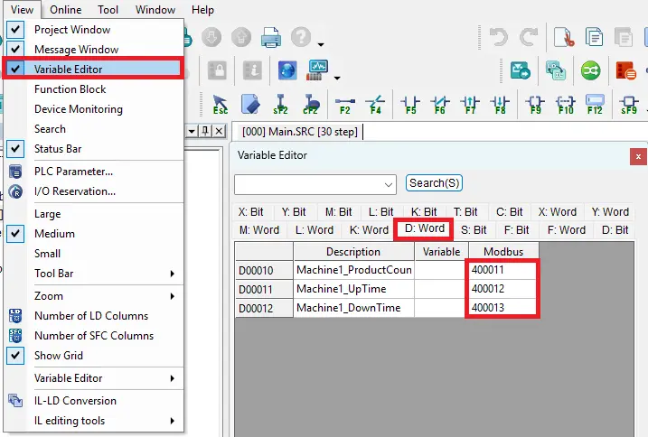
MQTT Publisher Configuration
This guide explains how to configure the cMT-G01X Gateway HMI in EBPro by setting up the Maple PLC Ethernet protocol and connecting to a local MQTT broker server.
IIot Communication Gateway Configuration in EBPro
Follow this step by step guide for configuring the communication protocol and MQTT settings for the Gateway HMI in EBPro
Instructions: IIot Communication Gateway Configuration in EBPro
Add a New Project
– Select the cMT-G01X Gateway model
– Click OK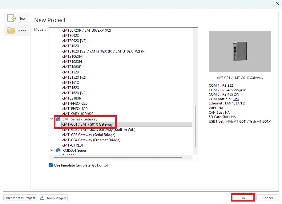
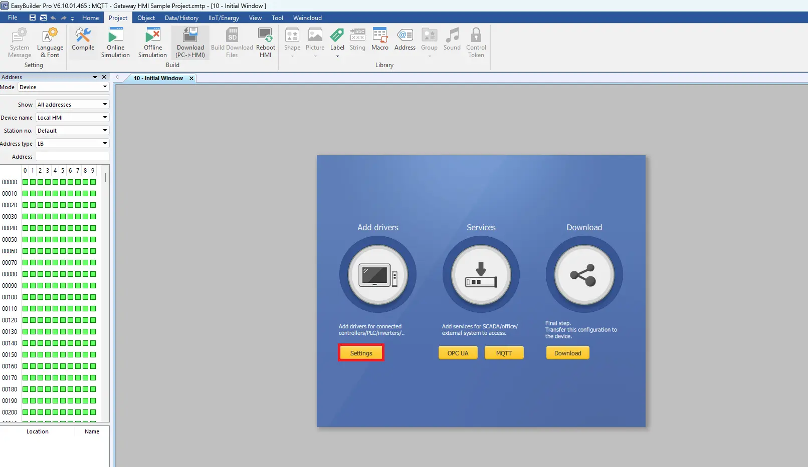
Configuring Communication Protocol
– Click the Settings button
Selecting the Communication Protocol
– Click the New Device/Server button
– Select Modbus > TCP/IP Master
– Choose Ethernet
– Choose Station Number: 0 (this must match the station number in MapleLogic, which is also 0)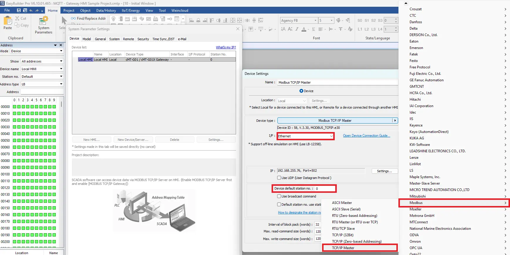
IP Address Settings
– Click Settings
– Enter the IP address of the PLC. 192.168.255.76 for this example.
– The default Port number is 502. DO NOT change this.
– In Click OK to save the settings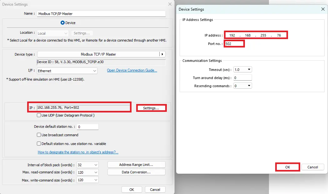
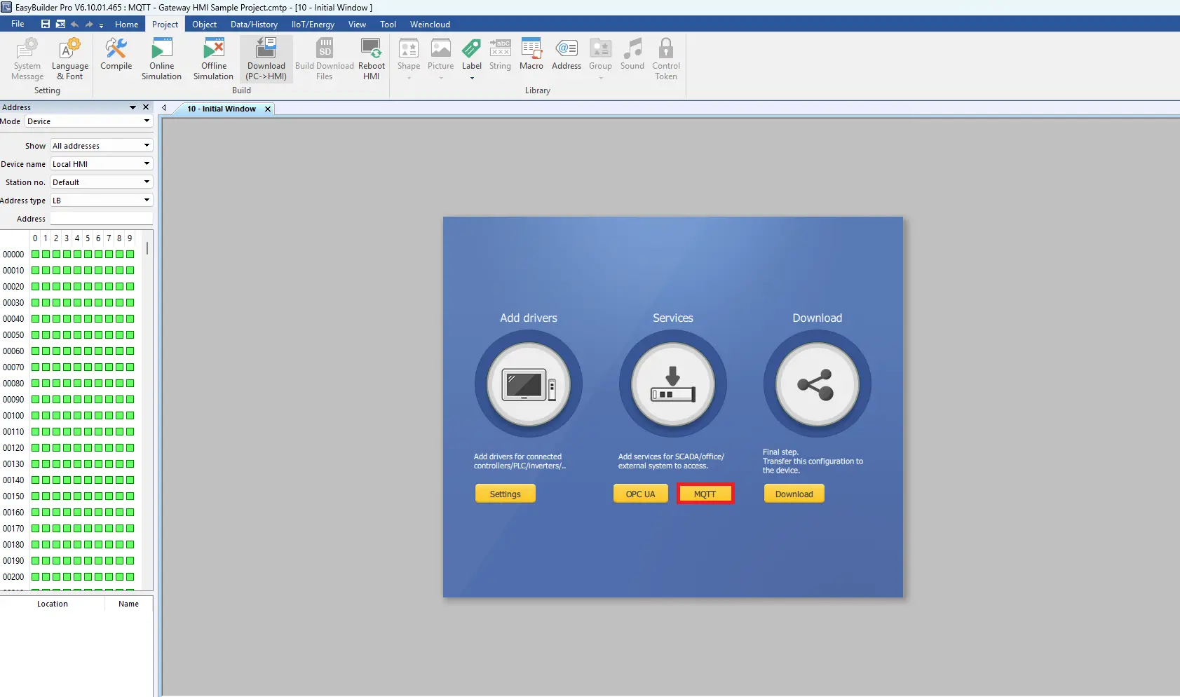
Configuring MQTT Settings
– Click MQTT to open these settings.
MQTT Server Properties
– Click Enable to open the server settings
– Click Settings… to open the properties
– Cloud service set to Generic
– Protocol can be left as default as MQTT v3.1
– Enter the IP address of the local MQTT server. 192.168.255.75 for this example. Port number is 1883.
– Click OK to save the settings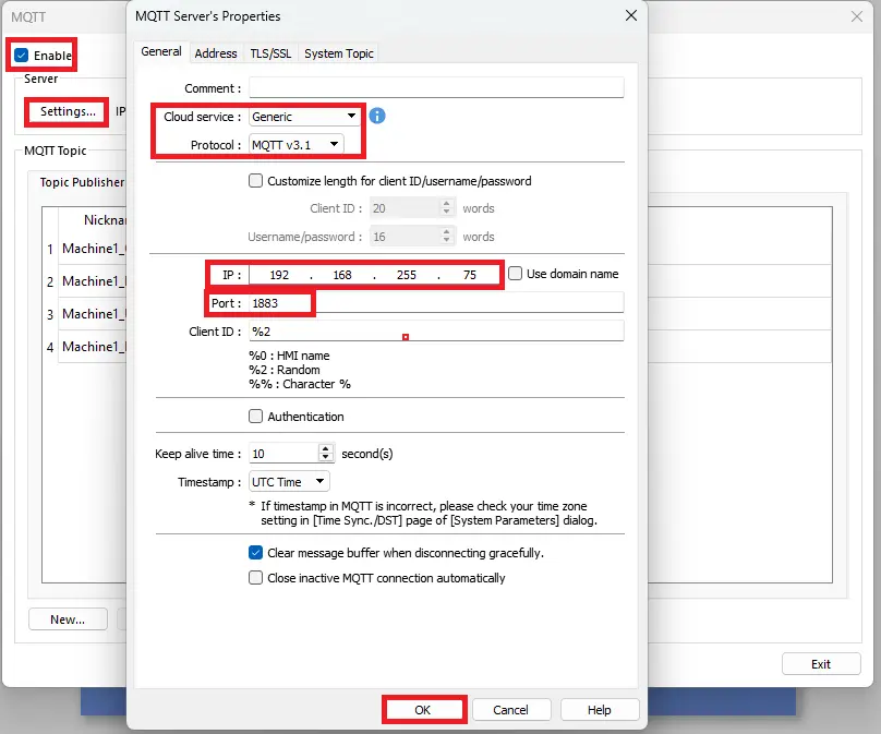
Add Machine 1 On Off Topic
– Select the Topic Publisher tab
– Add a topic named Machine1_OnOff and use a nickname of your choosing, it doesn’t have to match the topic name, but it does in this example.
– Check off Value-trigger based. This means that a message is published only when a tag’s value changes, instead of being sent continuously on a timed interval.
– Click OK to save the topic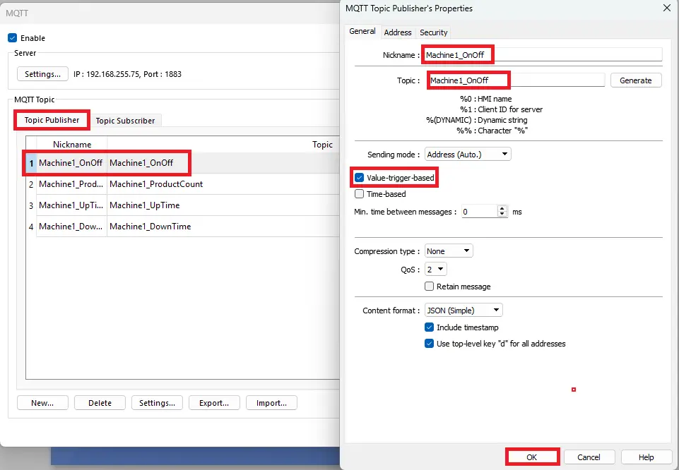
Machine 1 On Off Address
– Click the Address tab
– Select Bit
– Select the Modbus TCP/IP Master protocol as a device
– Select 0x_17 as an address.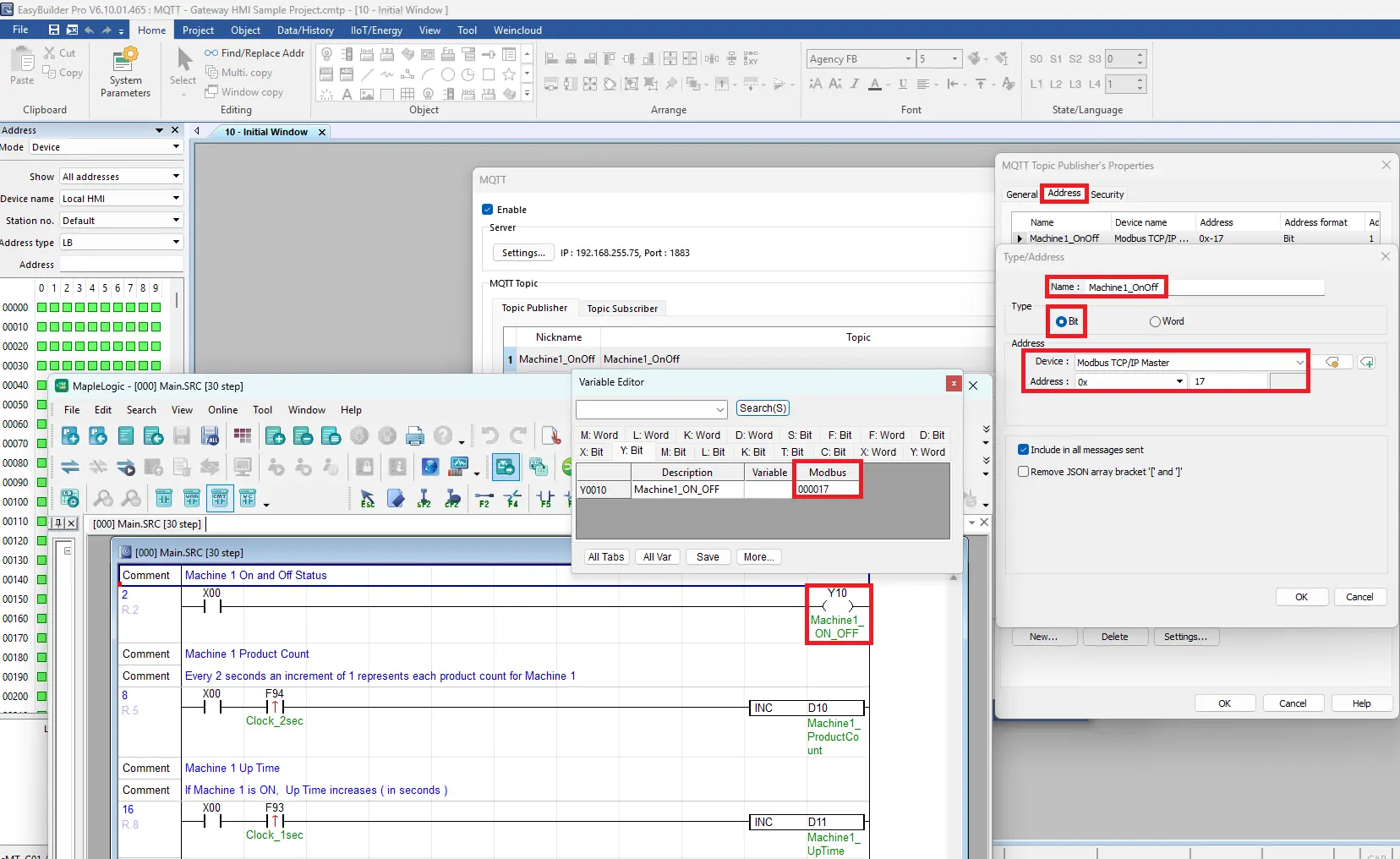
Machine 1 Product Count Address
– Click the Address tab
– Select Word
– Select the Modbus TCP/IP Master protocol as a device
– Select 4x_11 as an address. 4x is used for holding registers.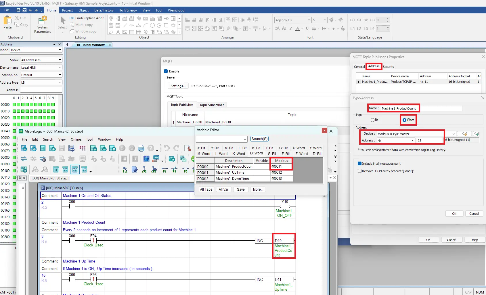
Downloading Projects
This guide explains how to download a project to the Gateway HMI in EBPro and download a PLC program in MapleLogic.
Downloading Projects in EBPro and MapleLogic
Follow this step-by-step giude for downloading projects in EBPro and MapleLogic
Instructions: Downloading Projects in EBPro and MapleLogic
Downloading Project to Gateway HMI
– Click the Download button on the toolbar
– Enter the IP address of the Gateway HMI
– Click Download to begin the processs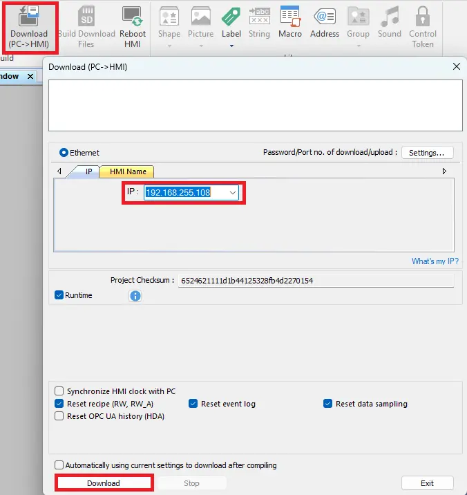
MapleLogic – Online
– Select Online on the toolbar
– Select Connect Option to open the communication setup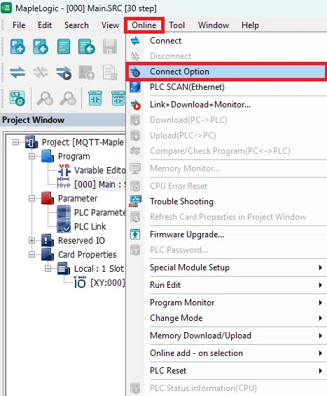
Choosing Ethernet
– Select Ethernet ( USB is also an option, ethernet will be used in this example)
– Enter the IP address of the PLC
– Click OK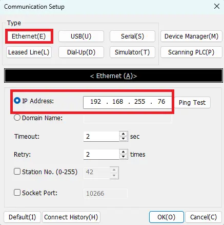
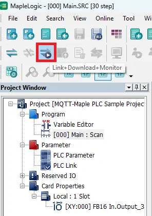
Link+Download+Monitor
– Click the Link+Download+Monitor button on the tool to download and monitor the project online
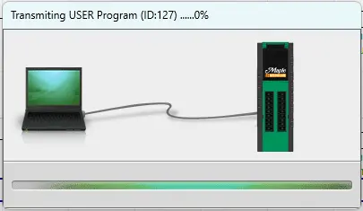
Transmission to PLC
– Once you click download transmission will begin to the PLC
RUN mode
– A prompt will pop up once the transmisssion completes to put the PLC into RUN mode
– Click YES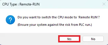
PLC Program Online
– Once the download process completes, and selecting RUN mode the logic will be activated and live values can be viewed in MapleLogic
– A PLC indicator will pop up to switch from RUN to STOP mode and display that the PLC is OK
– In the Message Window on the bottom, is the view of the PLC’s status and will indicate everything is running smoothly.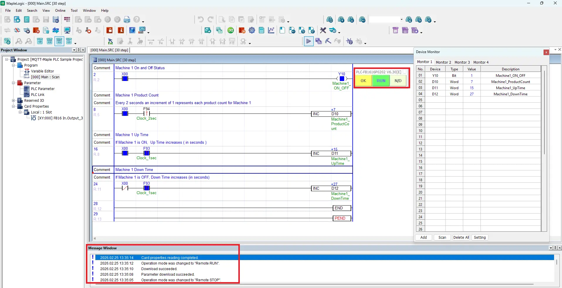
Live Simulation
This guide explains how to configure MQTT Explorer to connect to a local Mosquitto broker using the PC’s IP address (192.168.255.75) and port 1883, allowing users to monitor published topics. It also describes the live data flow where the PLC updates values, the Gateway polls via Modbus, publishes changes to the MQTT broker, and MQTT Explorer subscribes and displays the updates in real time.
MQTT Explorer Configuration
Follow this step-by-step guide for configuring MQTT Explorer and how to monitor live MQTT topics.
Instructions: MQTT Explorer Configuration
Add MQTT Connection in MQTT Explorer
– Choose the MQTT Broker Server (local MQTT Mosquitto server host url in this example: 192.168.255.75)
– 1883 is the port number
– Save the settings
– Click Connect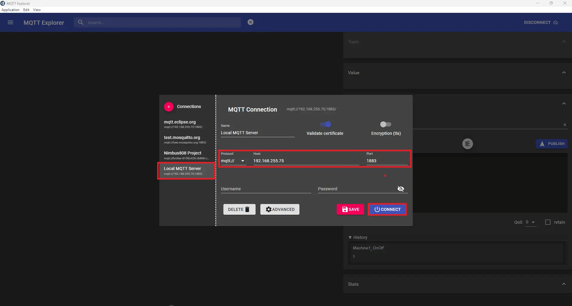
Viewing Topics
– Now view MQTT Explorer after connecting to the local MQTT broker server.
– If the MQTT configuration and mosbus addressing were done correctly, all of the topics can be monitored here.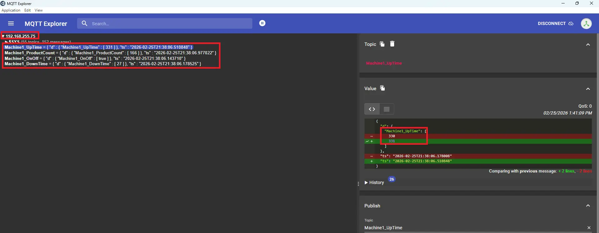
Below is a live simulation showing PLC logic update values in MapleLogic, Gateway detects change via Modbus polling, the Gateway publishes via MQTT, the broker routes the message, and subscriber (MQTT Explorer) receives and displays it.
The live simulation begins with the local Mosquitto broker running and waiting for client connections. The PLC switches from STOP to RUN mode, activating the ladder logic. When Y10 turns on, uptime and product count increment; when off, downtime increments instead.
The Gateway HMI continuously polls the PLC using Modbus TCP/IP, monitored through cMT Diagnoser. The cMT-G01X acts as Modbus Master, while the PLC responds as Modbus Slave.
The gateway stores register values internally and detects changes during continuous polling.
When a configured tag changes, the gateway publishes the updated value to the MQTT broker.
The broker simply routes messages to subscribed clients without modifying any data.
MQTT Explorer subscribes to topics and displays timestamps, payloads, and topic structures.
When messages arrive, MQTT Explorer updates instantly, completing the PLC-to-MQTT data flow.
Recap
This tutorial demonstrated how a Maple Systems PLC can control a machine locally while publishing real-time production data, such as run status, product count, uptime, and downtime, through MQTT to a central broker for plant-wide visibility.
It walks through the complete setup, including PLC ladder logic in MapleLogic, Gateway MQTT configuration in EBPro, network architecture, project downloads, and live monitoring in MQTT Explorer, showing how data flows from PLC to Gateway using Modbus TCP/IP Protocol to the broker, and finally to subscribers for real-time dashboards and analytics.
Next Steps
Pactical next steps would be to expand from monitoring to integrating the MQTT data into a SCADA system, cloud platform, or analytics tool for OEE tracking, downtime analysis, predictive maintenance, and automated reporting. Do this by implementing alarm management, secure MQTT communication (TLS, authentication), network segmentation, and data buffering to ensure reliability during outages.
Finally, consider adding more machines, standardizing tag structures, implementing edge computing logic in the gateway, and aligning with industry standards (ISA-95, OPC UA integration, or Sparkplug B) to build a scalable and future-proof architecture.
Sample Project
This integration tutorial uses these MapleLogic and EBPro sample projects.
Resources & Documentation
The following guides and documentation are specific to the hardware used in this integration tutorial and will help you with setup, configuration, and programming:
- MapleLogic User Manual
- Micro PLC User Manual
- PLC-FB1616P0202 Datasheet
- cMT Series G01X/G02X User Manual
- cMT-G01X Datasheet
- EBPro Programming Manual
Looking for additional learning resources? Explore our library of tutorials, example projects, and software tools to help you get the most out of your system:
Also, browse our Support Center for a complete list of installation guides, FAQs, and additional technical documentation.
About the Author
Trusted source for industrial automation & control solutions
Follow Maple Systems:
Share:


