In a manufacturing facility, a Maple Systems HMI+PLC combo unit collects real-time data from a production machine, including cycle counts, machine status, fault conditions, and operator inputs. Instead of storing this information locally, the unit publishes the data to an MQTT broker over the plant network or through a secure internet connection.

A cloud platform, SCADA system, or remote dashboard subscribes to the MQTT topics so engineers, maintenance teams, and managers can monitor machine performance from anywhere without connecting directly to the equipment.
This approach gives teams immediate visibility into production performance and equipment health across multiple machines or facilities. Maintenance teams quickly identify downtime events, analyze trends, and resolve issues faster, while management reviews accurate production metrics to guide decision-making. MQTT simplifies integration because it uses minimal bandwidth and supports scalable communication between many devices and centralized systems, making it ideal for Industrial IoT applications.

The image above illustrates a sample MQTT dashboard layout. It presents an industrial-style machine monitoring interface that highlights production performance and MQTT communication status.
On the left side, a large bar chart compares product counts for eight machines. Machine 1 leads with approximately 9,200 units, while Machine 5 trails at about 2,100 units. At the top right, a green MQTT status indicator confirms the connection, and the “MQTT ERROR STATUS” field shows “No Errors,” indicating a healthy broker connection.
Below that section, the dashboard displays eight machines in two columns. Each machine includes a green status graphic and a toggle-style indicator showing that the machine is ON.
At the bottom, individual boxes display each machine’s product count along with realistic uptime and downtime values, such as 7h 30m uptime and 1h 10m downtime. A highlighted label identifies Machine 1 as the best-performing machine, matching the highest value in the product count chart.
Software Required
Hardware Required
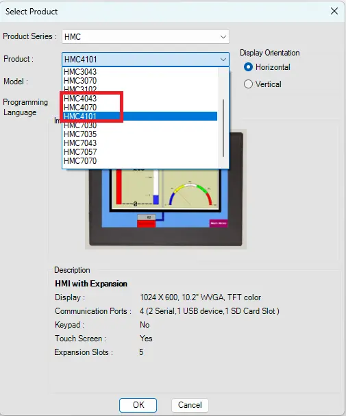
- HMI+PLC Combo Unit (HMC4101A-M used in this example. Any HMC4000 Series model is configurable as an MQTT broker)
- any MQTT Broker (I’ll be using a local Mosquitto MQTT server on a PC as an example).
- (Optionally) an MQTT client software (I’ll be using MQTT Explorer for this tutorial).
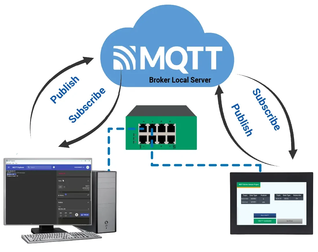
Network Diagram

The diagram illustrates the network configuration used in this simulation. A locally hosted MQTT broker acts as the central message server. Both the PC running MQTT Explorer and the HMI+PLC combo unit connect to the same plant network through a standard Ethernet switch. All devices operate on the same IP subnet.
In this setup, both the PC and the HMI+PLC act as MQTT clients. Each device connects to the broker and publishes or subscribes to configured topics. When the HMI+PLC publishes data, MQTT Explorer receives it through the broker. When MQTT Explorer publishes a message, the broker forwards it to the HMI+PLC.
All communication follows the MQTT publish/subscribe architecture. Each client connects directly to the broker rather than to other devices. When a device publishes data to a topic, the broker receives the message and distributes it to subscribed clients. The broker manages routing, session handling, and topic filtering to ensure that only appropriate subscribers receive the data. The HMI+PLC and the PC never communicate directly; the broker processes and forwards every message
MQTT Configuration
This section will walk you through the intial setup of a new project in MAPware-7000 using an HMC4000 series HM+PLC combo unit. It’ll also go over MQTT configuration and tag creation.
Initial Setup in MAPware-7000
Follow this step by step guide for getting started with a new project and MQTT configuration in MAPware-7000.
Instructions: Initial Setup in MAPware-7000
Start a New Project in MAPware-7000
– In the new project select an HMC4000 Series
MQTT Broker Settings
– On the left side select the MQTT Broker folder
– MQTT cloud set to External
– MQTT Protocol set to MQTT v3.1.1 (newer version)
– Broker/Server Address is the IP address of the PC being used in this example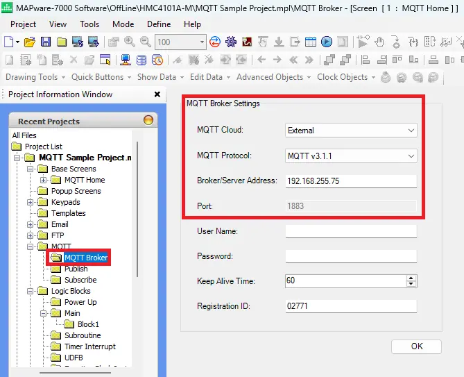
MQTT Publish Settings
– On the left side select the Publish Folder
– Add a Topic Name and Description
– They will be added to Current Topics
– Click Edit to make changes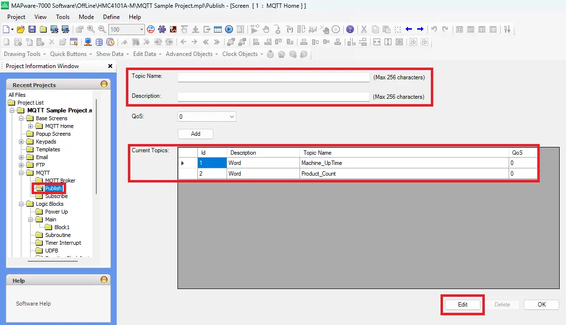
MQTT Subscribe Settings
– On the left side select the Subscribe Folder
– Add a Topic Name and Description
– They will be added to Current Topics
– Click Edit to make changes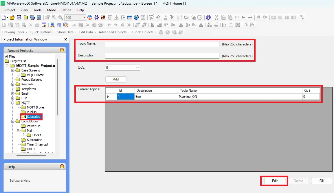
Adding Up Time Tag
– On the left side select the Tags folder
– In this example the tag will be named Machine_UpTime
– Register Type set to WORD
– Select Publish for MQTT and the Machine_UpTime Topic Name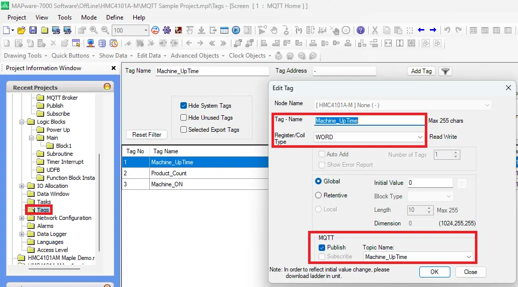
Adding Product Count Tag
– On the left side select the Tags folder
– In this example the tag will be named Product_Count
– Register Type set to WORD
– Select Publish for MQTT and the Product_Count Topic Name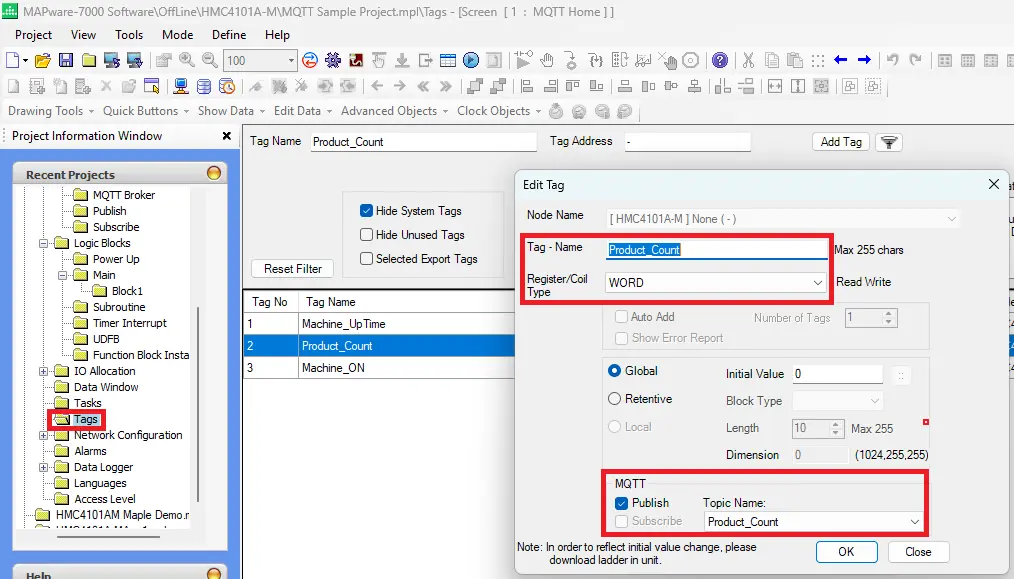
Adding Machine On Tag
– On the left side select the Tags folder
– In this example the tag will be named Machine_ON
– Register Type set to BOOL
– Select Subscribe for MQTT and the Machine_ON Topic Name
HMI+PLC Project Build
This section will walk you through the project build for objects used in MQTT communication between MAPware-7000 and the MQTT server using an HMC4000 series HMI+PLC combo unit.
MQTT Project Build in MAPware-7000
Follow this step by step guide for building a specific MQTT project in MAPware-7000
Instructions: MQTT Project Build in MAPware-7000
Add a Base Screen
On the left side right click on Base Screen and name it MQTT Home
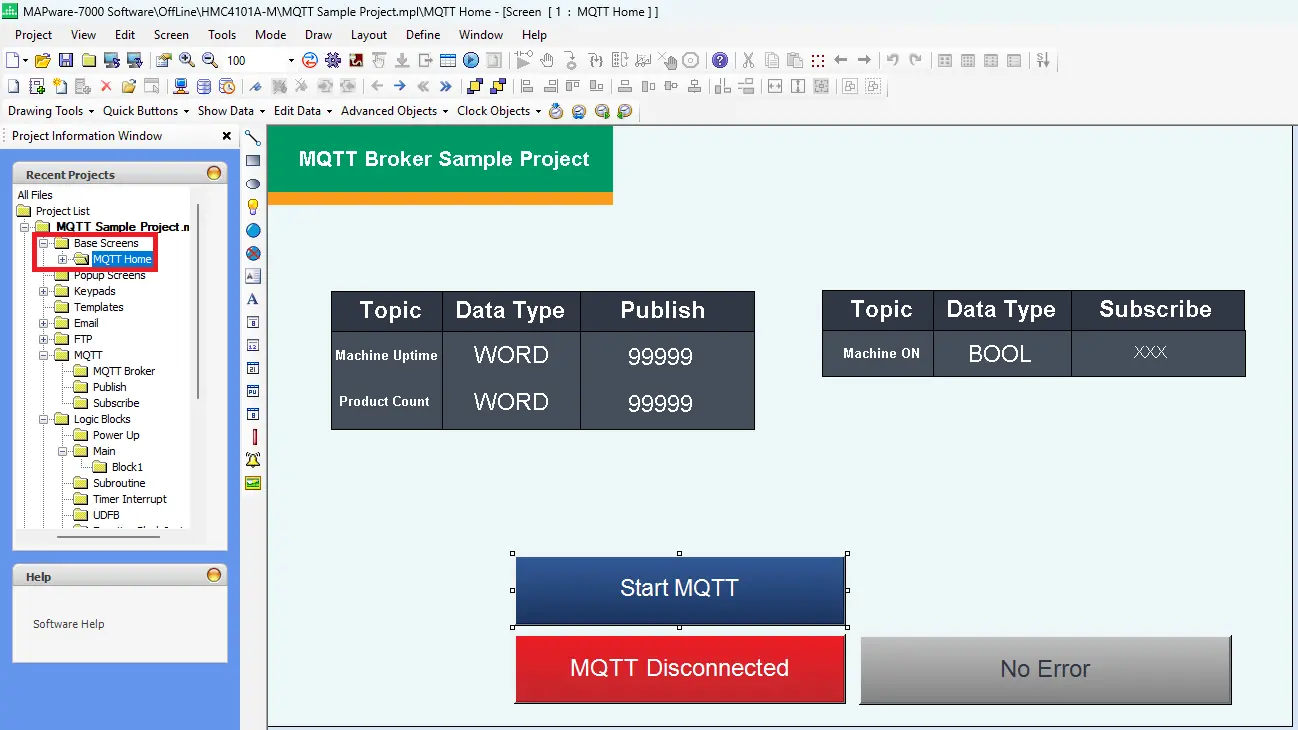
Add a Word Lamp for MQTT Start and Stop
– Navigate to Advanced Objects > Buttons > Word Action > Write Value to Tag
– Edit the On Text to Start MQTT
– Value Data Type to Unsigned
– For Tag Name, choose the system tag MQTT_Run_Stop (SW0278)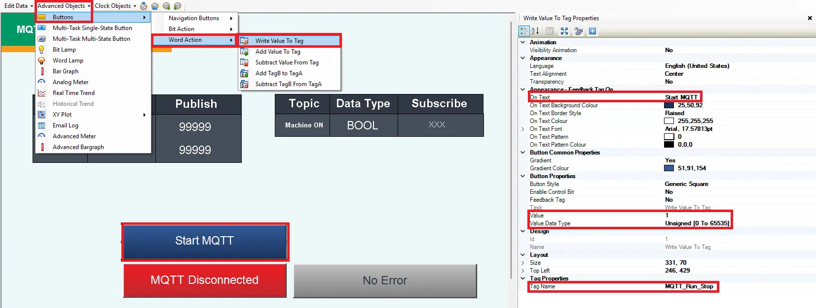
Add a Word Lamp for MQTT Status
– Navigate to Advanced Objects > Word Lamp
– Edit the State Properties (2 States)
– For Tag Name, select the system tag MQTT_Status (SW0276)
The next step will go over editing the state properties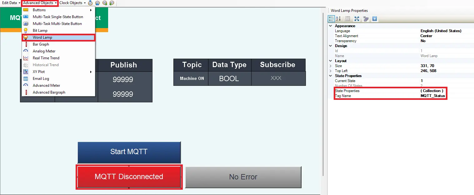
Edit State 1 of MQTT Status Word Lamp
– Change the color to red to represent when MQTT is disconnected
– Edit text to MQTT Disconnected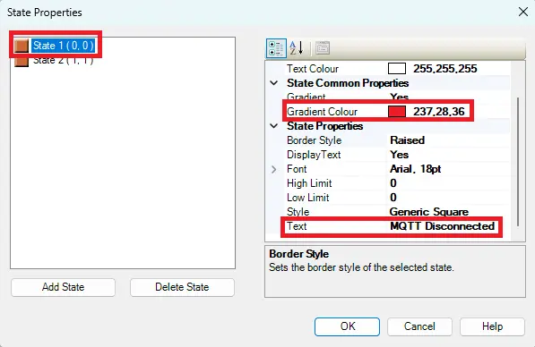
Edit State 2 of MQTT Status Word Lamp
– Change the color to green to represent when MQTT is connected
– Edit text to MQTT Connected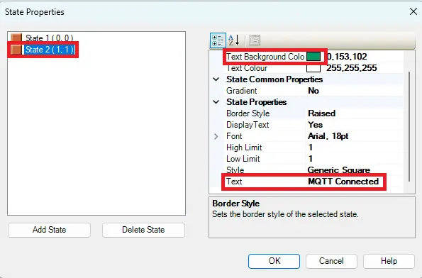
Add Word Lamp for Error Status
– Navigate to Advanced Objects > Word Lamp
– Add 8 states to display the 8 different error code values for the connection
– State 1 Text – No Error
– State 2 Text – Connection Refused
– State 3 Text – Remote Host closed
– State 4 Text – Host Not Found
– State 5 Text – Socket Access Error
– State 6 Text – Socket Resource Error
– State 7 Text – Socket Timeout Error
– State 8 Text – Socket Error
Review the next step to see all the error codes as well as their detailed descriptions and common causes.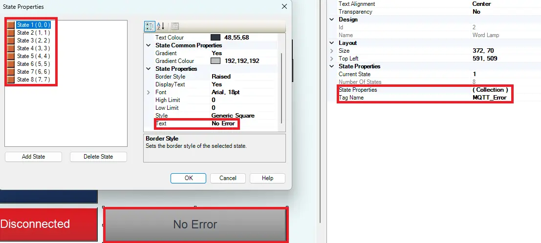
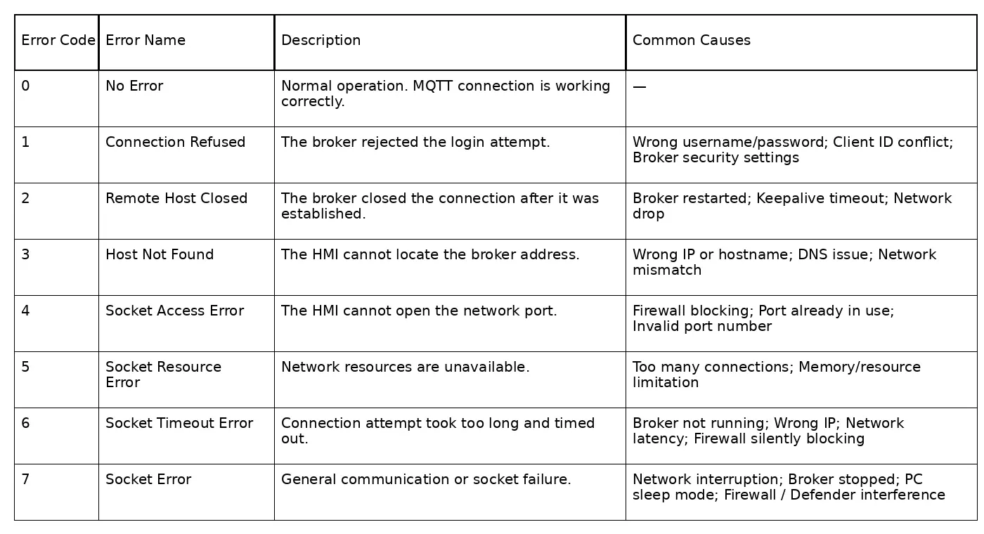
MQTT Error Codes
– Review the table below to see all the MQTT error codes, descriptions and common causes.
Add Numeric Entry for Machine Up Time Word
– Navigate to Edit Data > Numeric Entry
– Edit Data Type to Unsigned
– For Tag Name, select the user defined tag Machine_UpTime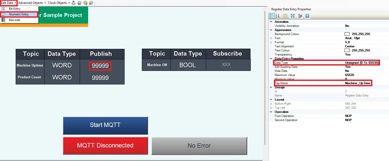
Add Numeric Entry for Product Count Word
– Navigate to Edit Data > Numeric Entry
– Edit Data Type to Unsigned
– For Tag Name, select the user defined tag Product_Count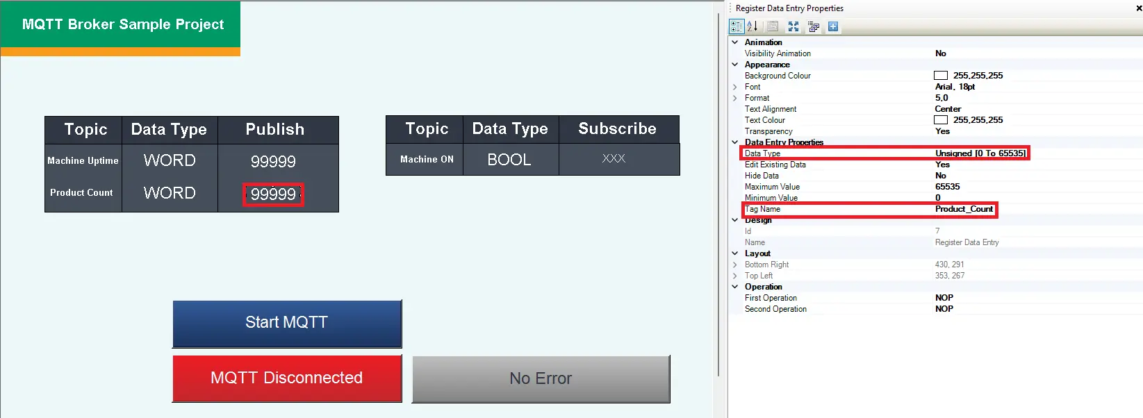
Add Bit Display for Machine On Bool
– Navigate to Show Data > Bit Display
– For Tag Name, select the user defined tag Machine_ON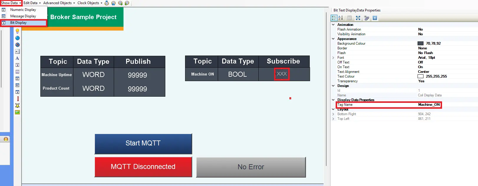
Downloading Project
Now download the project to the HMI+PLC combo device.
Downloading the Project in MAPware-7000
Follow this step by step guide for downloading a project to the HMI+PLC Combo device via ethernet.
Instructions: Downloading the Project in MAPware-7000
Compile the Project
– Click the gears icon on the tool to compile the project
– In the Compile window at the bottom, it will indicate that there are No errors detected if there are no errors.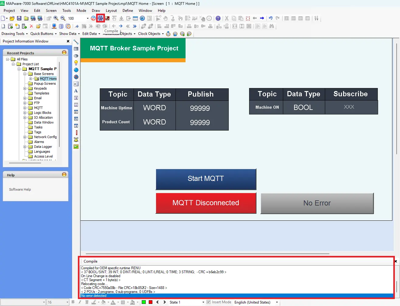
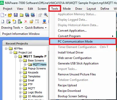
PC Communication Mode
Navigate to Tools > PC Communication Mode
Choosing a Communication Setting
– In this example, choose Ethernet, and enter the IP address of the HMI+PLC combo device. You could also choose USB.
– You must click OK to save the settings.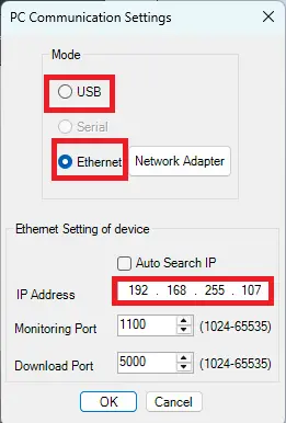
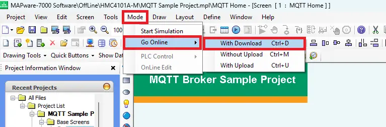
Opening Download Window
– Navigate to Mode > Go Online > With Download
Download Settings
– Check to make sure the IP address is correct
– Check off Application
– Click Download to begin the process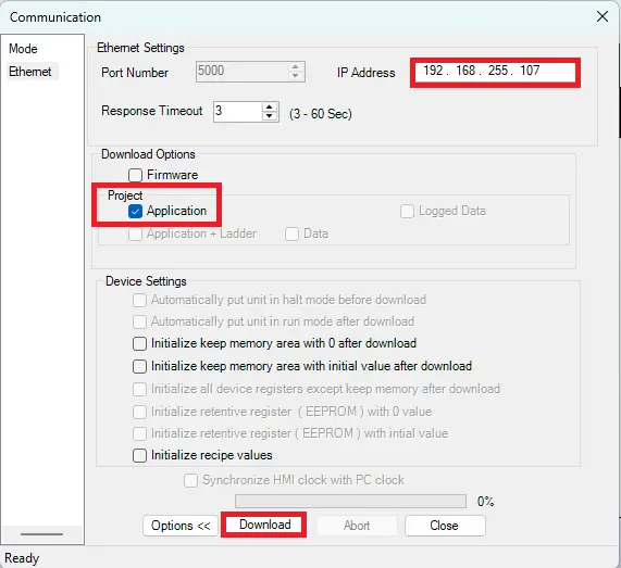
Downloading the Project
– It will run through the download process
– Once it gets to 100%, it’ll indicate the download is complete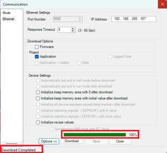
Live Simulation
This section explains how to configure MQTT Explorer to connect to a local Mosquitto broker and verify communication with the HMI+PLC combo unit. It demonstrates both publish and subscribe functionality, showing how data sent from either device is routed through the broker and reflected in real time on the other client.
MQTT Explorer Configuration
These steps cover connecting MQTT Explorer to the local broker and testing publish and subscribe communication with the HMI+PLC combo unit.
Instructions: MQTT Explorer Configuration
Initial Setup
– Open MQTT Explorer
– Choose the MQTT Broker Server (local MQTT Mosquitto server host url in this example: 192.168.255.75)
– Port 1883
– Save the Settings
– Click Connect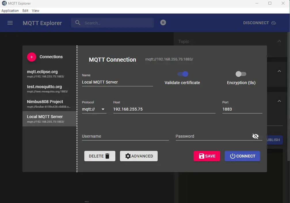
Test Publish
– On the right is an online view of the project on the HMI+PLC combo unit using VNC Viewer.
– On the left is MQTT Explorer after connecting to the local MQTT broker server.
– The Product_Count is published in MAPware-7000 (HMI+PLC combo device) with a value of 50 and it can be viewed in MQTT Explorer as well.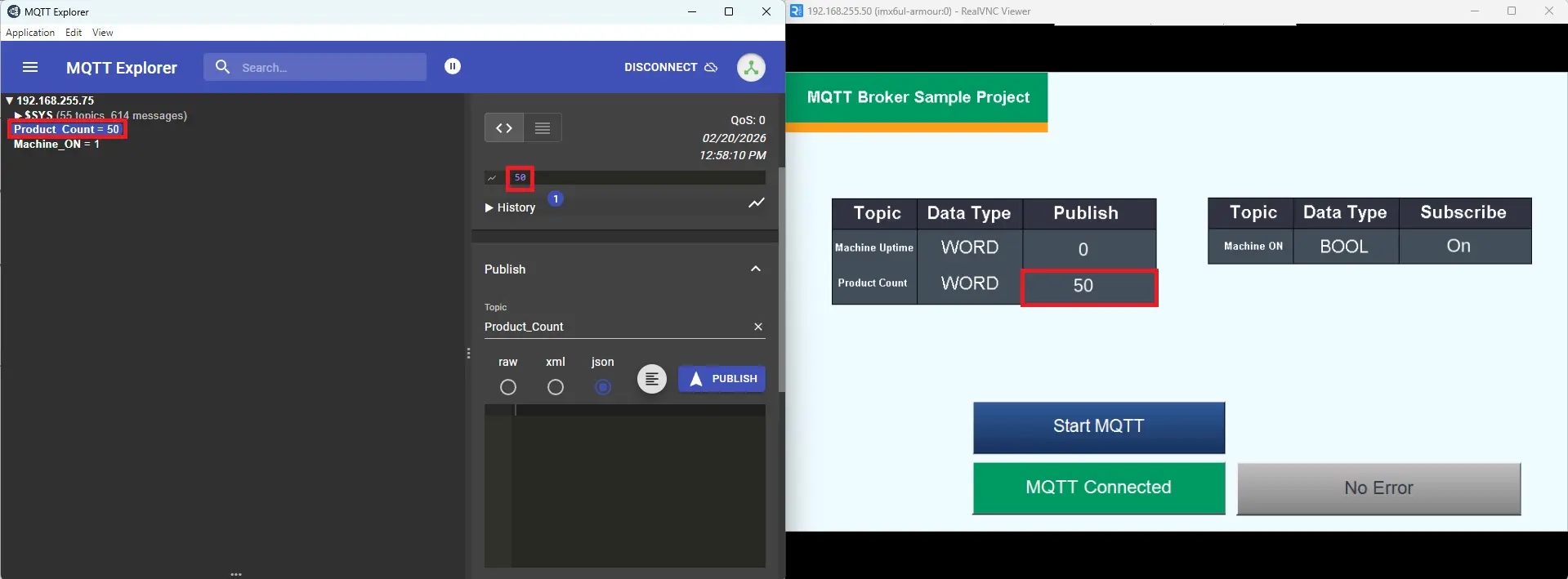
Test Subscribe
– A value of 1 is entered on the broker side (MQTT Explorer), this turns on the bit on the HMI+PLC combo device
Please watch the simulation below to see how the MQTT system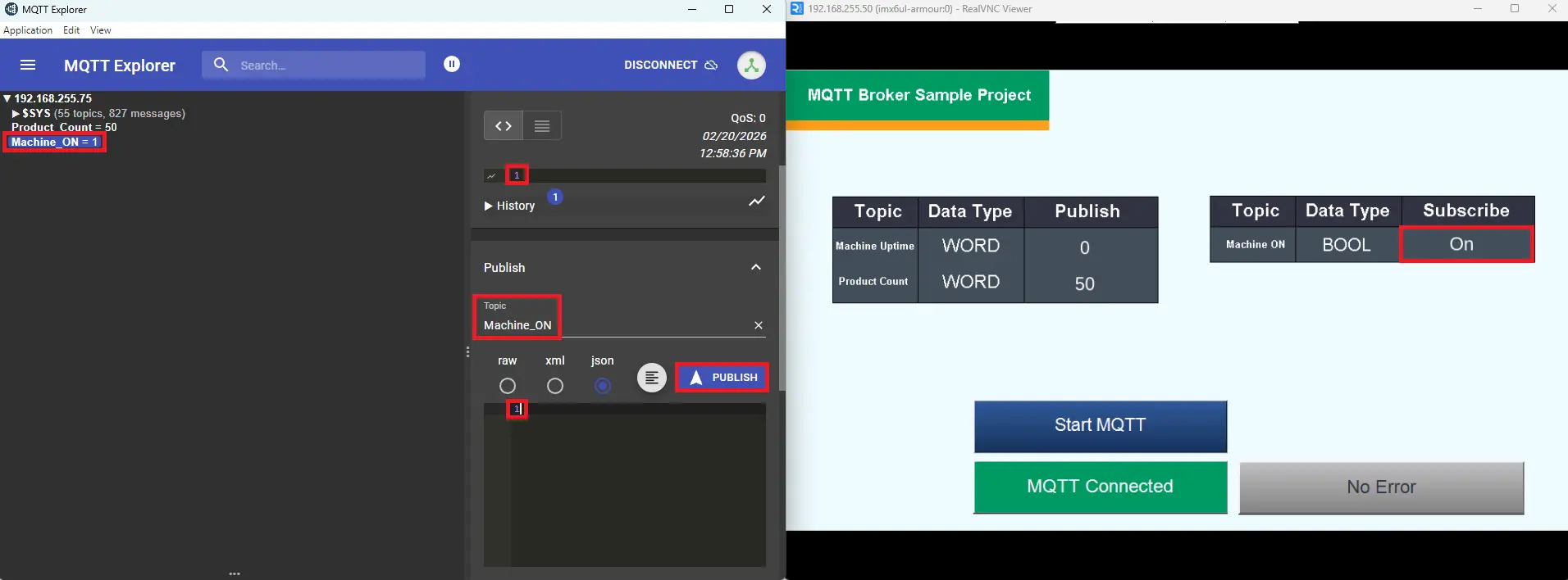
This video above shows a live simulation of an MQTT system using:
- A local Mosquitto MQTT broker
- An HMI + PLC project
- MQTT Explorer for monitoring
- A command terminal running the local broker
Here’s what happens step-by-step:
- MQTT Broker Starts (Mosquitto)
- At the bottom right of the screen, a terminal window shows Mosquitto running locally. The broker starts successfully and waits for client connections.
- This broker acts as the message middleman between the HMI+PLC combo unit and MQTT Explorer.
- MQTT Explorer Connects
- On the bottom left side, MQTT Explorer connects to the Local MQTT Server
- HMI+PLC Project Connects to Broker
- The “Start MQTT” button is pressed
- Status changes from “MQTT Disconnected” (red)
to “MQTT Connected” (green)
- MQTT Explorer subscribes to the BOOL topic
- Entering Machine_ON as the topic, type 1 (on) into the json field and click Publish.
- MQTT Explorer connects to the Mosquitto broker and subscribes to the topic where the HMI+PLC is publishing the BOOL value (for this example, a machine ON/OFF signal).
- It’s also displayed in the Online view in MAPware-7000 Data Monitor as TRUE
- HMI+PLC Publishes Product Count to the broker
- In the top right corner, a value of 100 is entered into theProduct_Count.
- It publishes that value to the configured topic Product_Count
- The Mosquitto broker receives the message
- MQTT explorer , which is subscribed to to that topic, receives and displays it.
- It is also displayed in the data monitor (MAPware-7000) in the top right corner of the screen.
MQTT Explorer typically automatically subscribes to topics so it can display live updates. So when you publish a value from MQTT Explorer:
- MQTT Explorer sends the message to the broker.
- The broker forwards that message to all subscribed clients.
- That includes: The HMI+PLC (if it is subscribed) and MQTT Explorer itself (since it’s also subscribed)
When you enter a value in the HMI + PLC under Product_Count and it appears in MQTT Explorer, that means the HMI+PLC is publishing that value to the broker.
HMI+PLC > MQTT Publish > Broker > MQTT Explorer
Recap
In this walkthrough, we learned how a Maple Systems HMC4000 Series HMI+PLC combo unit can be configured to communicate using MQTT for real-time industrial data monitoring. Using MAPware-7000, we set up an external MQTT broker connection, created publish and subscribe topics, and assigned tags such as Machine_UpTime and Product_Count (published) and Machine_ON (subscribed). We also learned how to use system tags like MQTT_Run_Stop and MQTT_Status to control and monitor the broker connection, as well as how to build an HMI screen with status indicators, error displays, and data entry objects to visualize and test MQTT communication directly on the device.
We also learned how MQTT enables two-way communication between field equipment and remote systems. By connecting the HMI+PLC to a Mosquitto broker and monitoring activity with MQTT Explorer, we saw how published data flows from the HMI+PLC to the broker and then to subscribed clients, and how commands sent from the broker can update the HMI in real time. This demonstrated how MQTT provides a lightweight, scalable solution for Industrial IoT applications, delivering immediate visibility into machine performance while simplifying integration with cloud platforms, SCADA systems, and remote dashboards.
Next Steps
The practical next steps would focus on moving from basic MQTT communication testing to a fully deployed Industrial IoT solution.
First, expand beyond simulation into real machine integration. Connect the HMI+PLC to actual production equipment and map real signals such as cycle counts, downtime events, alarms, and fault codes to MQTT publish topics. Implement structured topic naming (for example, by machine name or production line) to support multiple devices. At the same time, enable broker authentication, user credentials, and encrypted connections (TLS) to secure communication, especially if data will travel outside the plant network. Testing with multiple HMI+PLC units would validate scalability and network performance.
Next, integrate the MQTT data into higher-level systems for actionable insights. Connect the broker to a SCADA platform, cloud dashboard, or database to log historical data, create trend analysis, and build KPI dashboards for OEE, uptime, and throughput. Configure alerts for downtime or fault conditions so maintenance teams can respond proactively. Finally, establish deployment standards documentation, reusable MAPware templates, topic conventions, and security policies, so the solution can be replicated efficiently across additional machines or facilities.
Sample Project
This integration tutorial uses the MAPware-7000 Sample Project.
Resources & Documentation
The following guides and documentation are specific to the hardware used in this integration tutorial and will help you with setup, configuration, and programming:
Looking for additional learning resources? Explore our library of tutorials, example projects, and software tools to help you get the most out of your system:
Also, browse our Support Center for a complete list of installation guides, FAQs, and additional technical documentation.
About the Author
Trusted source for industrial automation & control solutions
Follow Maple Systems:
Share:


