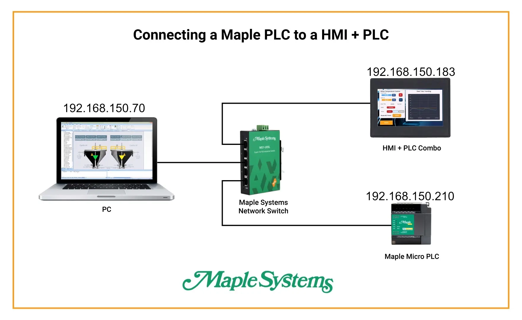
Imagine you’re in charge of an industrial production plant, where every machine on your assembly line is managed by a Modbus-compatible PLC. And you want all of these devices to connect to and be managed by a single overarching PLC, with some light logic in it, but also with a screen to display diagnostics, and offer HMI-like controls for this “master” PLC. A Maple Systems HMI + PLC combo unit (a.k.a. an “HMC”) would fit the bill perfectly. But how would you integrate a Maple Systems HMC with a Modbus PLC?

Software Required
Hardware Required
- Any Maple Systems HMI + PLC Combo Unit
- Any PLC that supports Modbus communications. I’ll be using a Maple Systems PLC for this tutorial
TCP/IP Connection (Ethernet)
This section explains how to establish a TCP/IP connection over Ethernet between your PLC and HMC. It covers the required settings on both sides, including network parameters, communication drivers, and protocol configuration.

PLC Configuration
We’ll start by configuring our PLC.
Instructions: PLC Configuration
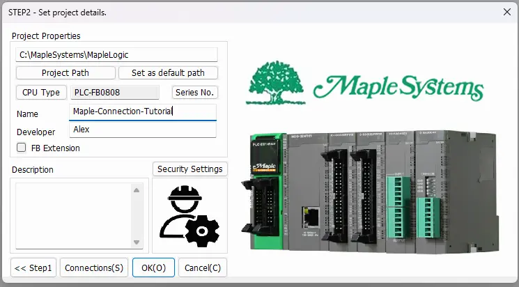
Initializing a new Project
Open up a new project in MapleLogic, select your PLC type (modular ES or micro FB), and name your project.
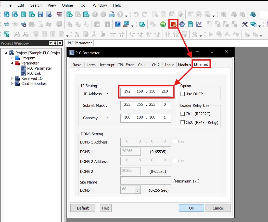
Configuring the PLC’s IP address
Open up the PLC parameters and go to the “Ethernet” tab, then change your PLC’s IP address to what you’d like. Be sure to take note of this IP address for when we configure the HMI + PLC side. Hit “OK” and save your new IP address.
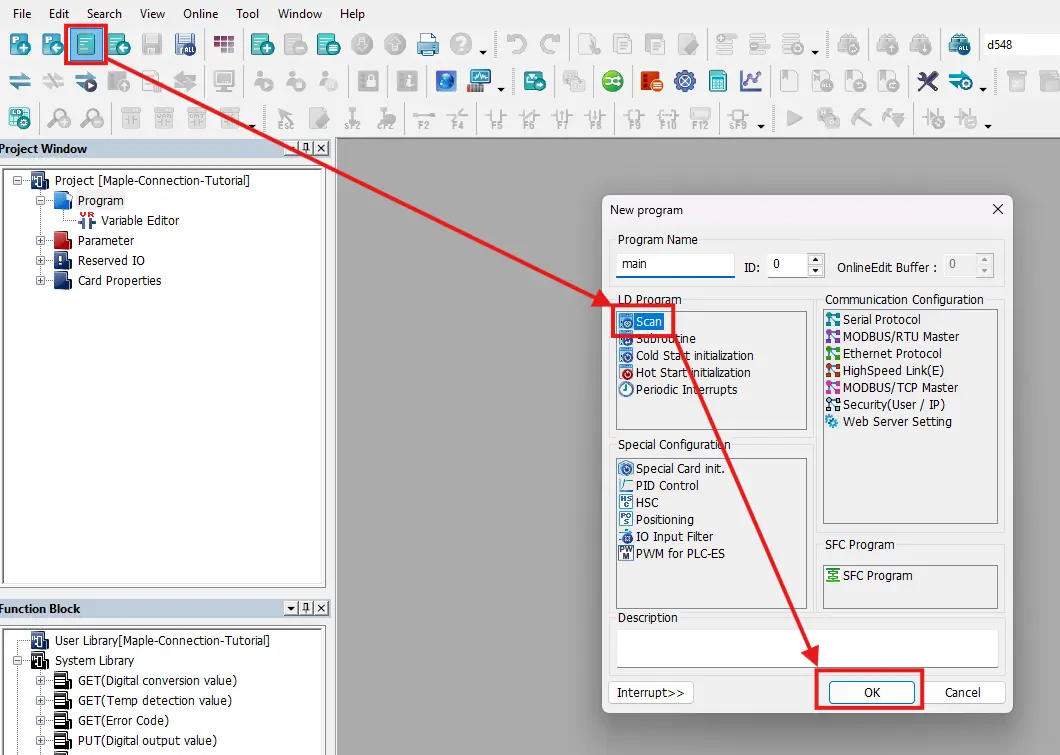
Create a base project
Finally, you’ll want to create a new main scan program in MapleLogic. The PLC project won’t compile or download properly if there isn’t a main scan program.
Connecting to the PLC
We’ll then want to make sure to connect our PLC to the computer with a mini-USB cable. We’ll also want to make sure to set MapleLogic to download via the USB cable like so
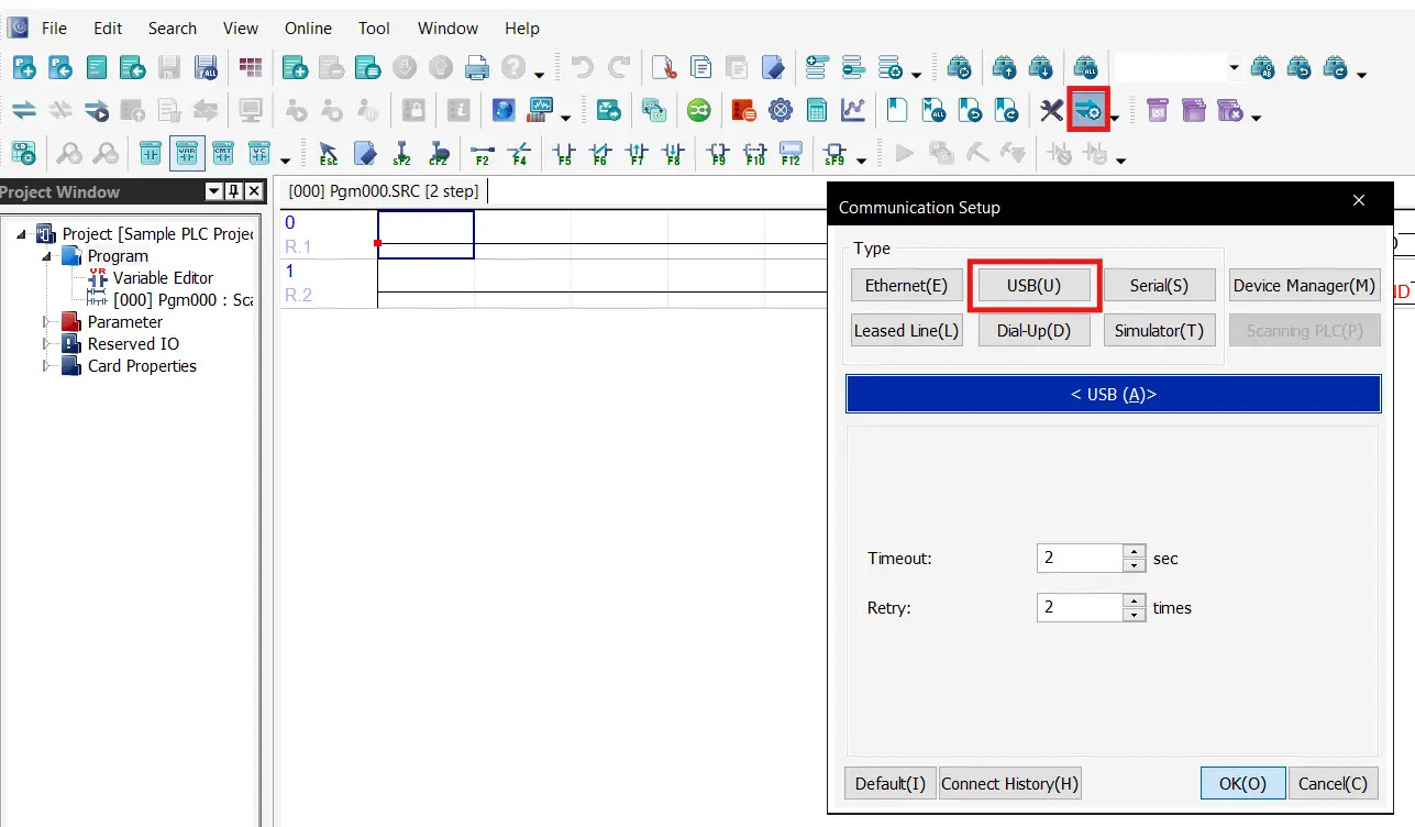
Link + Download + Monitor
Next, you’ll want to press the “Link + Download + Monitor” button and accept all the prompts.
HMC Configuration
Now we’ll move on to configuring the HMI + PLC combo unit for an Ethernet connection.
Instructions: HMC Configuration
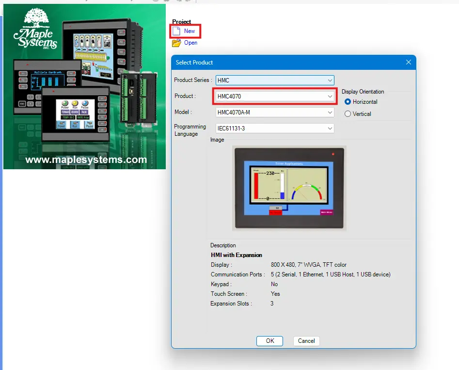
Create a new MAPware-7000 project
To start, we’ll make a new MAPware-7000 project, name it, and select our HMC model
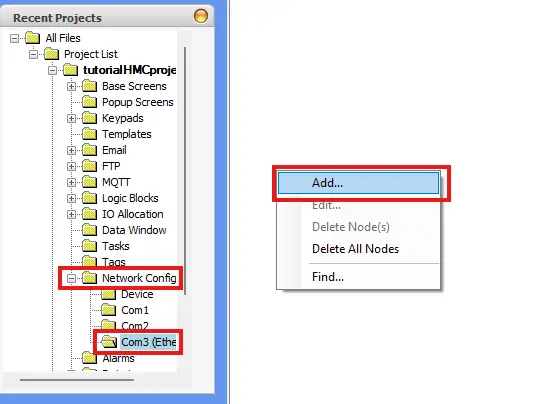
Adding a New Ethernet Connection
Then we’ll go to “Network Configuration > Com3 (Ethernet)” then we’ll right-click the page to add a new device connection.
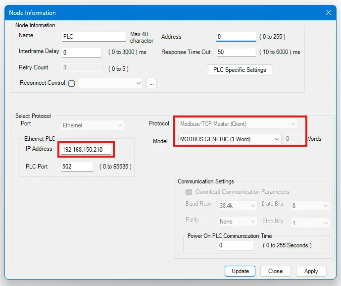
Configuring the Modbus Settings
Now we’ll configure this connection node, being sure to configure it as a Modbus Master node, and pointing it to the IP address we set our PLC to.
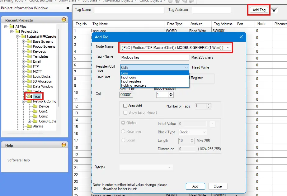
Adding Modbus Tags
Now that we have a communication node in our MAPware-7000 project, we can create tags on our device that are tied to Modbus addresses on our PLC. We’d do this by going to our tag database, and adding new tags under the node we just created.
Configure the HMC screen
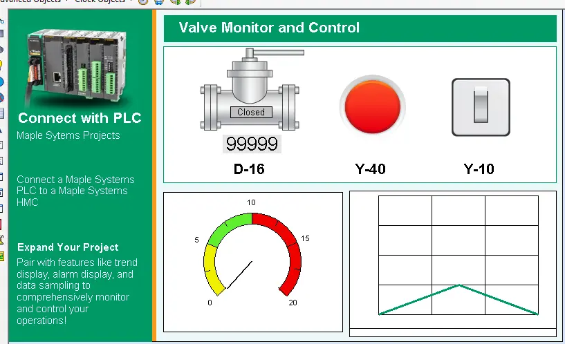
At this point we’ll want to display a handful of Modbus Tags on our HMC screen, so we’ll go ahead and make some more tags, and attach some MAPware screen objects to them.
RTU Connection (Serial)
This section outlines how to configure a serial RTU connection between your PLC and HMC. It covers RS-232 wiring, configuring communication parameters, setting the Modbus Slave ID on the PLC, and matching those settings on the HMC to ensure reliable serial communication.

PLC Configuration
As before, we’ll start with the PLC side of the connection, and configure our PLC for an RS-232 Serial Modbus connection.
Instructions: PLC Configuration
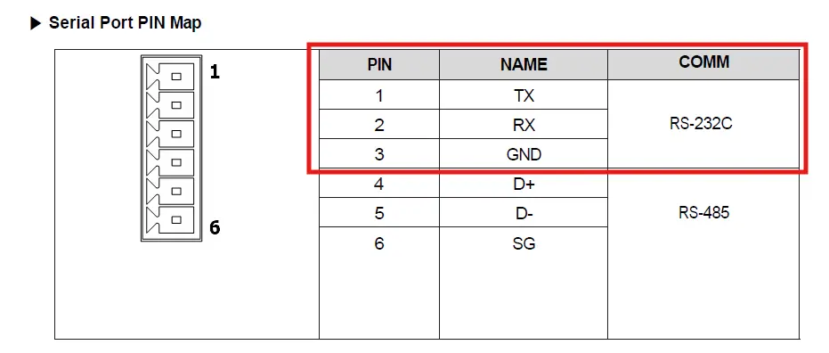
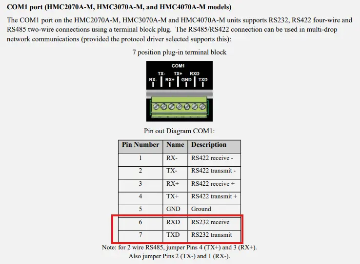
Wiring the PLC
To start, you’ll want to make sure to wire your PLC properly for a serial connection. On the CPU itself there’s a terminal block that allows for both RS-232 and RS-485 connections. The pinouts for these connections are outlined in the user manual for your PLC.
Noting our Serial Settings
Within the PLC Parameters of our MapleLogic project, we’ll want to go to the “ch 1” tab and take not of our serial settings (or tweak them to our liking)
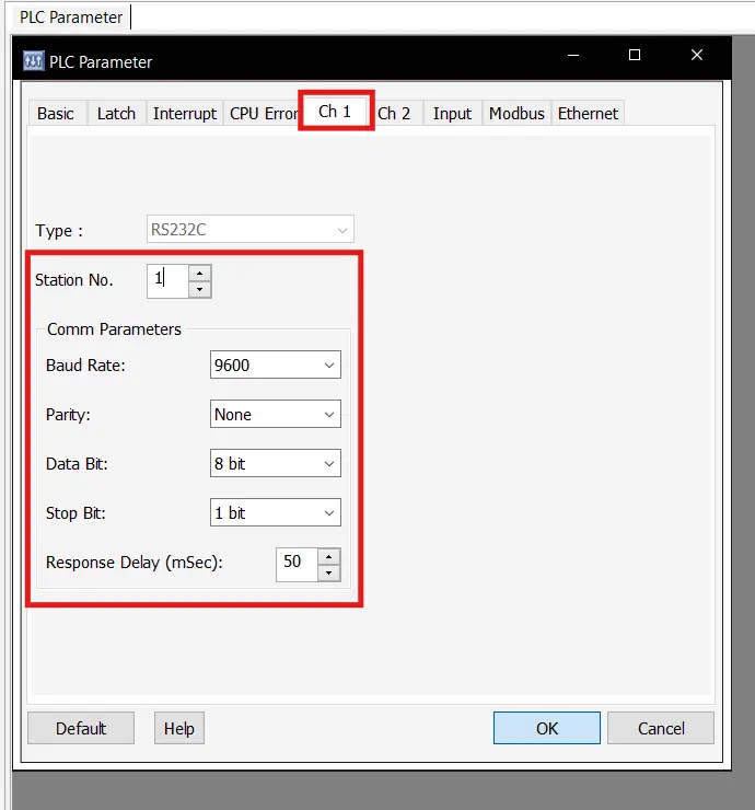
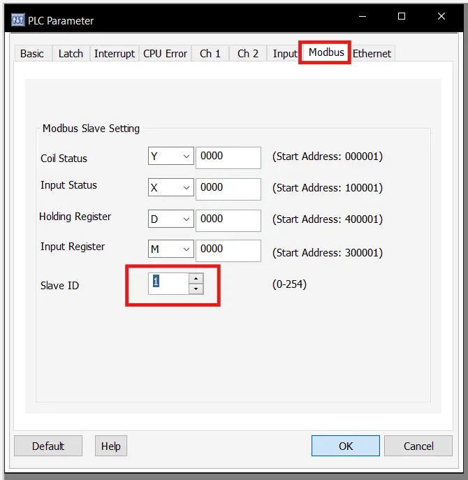
Configuring our Modbus Station ID
Next we’ll go to the Modbus tab and make sure the “Slave ID” is set to 1
Download our project
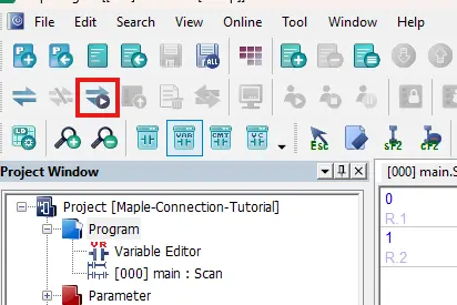
Once we’ve configured all the serial settings on the PLC, we’ll connect to our PLC and download to it the same way as before.
HMC Configuration
Now we’ll go over the differences when configuring the HMC for an RS-232 Serial connection.
Instructions: HMC Configuration
Wiring the HMI + PLC
To start, much like on the PLC side, we’ll want to attach our RS-232 wires to the proper terminal slots on our HMC’s COM 1 port.
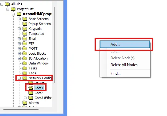
Adding a New Serial Connection
Much like the Ethernet Node, we’ll go to “Network Configuration > Com1” page, and right-click the page to add a new device connection.
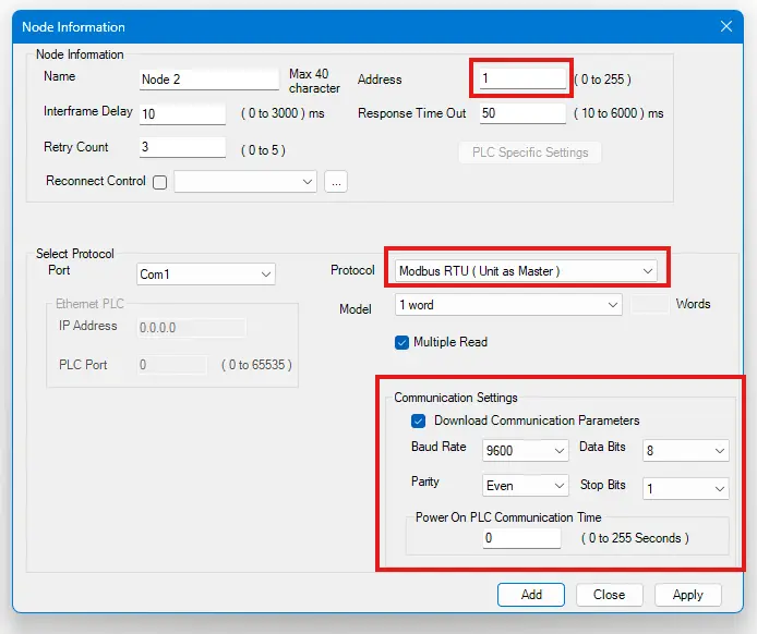
Configuring our Serial Connection
Now we’ll configure our new serial connection node. Be sure to register this node as a Modbus RTU (unit as Master) node, and make sure that the “Address” field matches the “Slave ID” from the PLC, and that all of the communication settings in the bottom-right match those on the PLC.
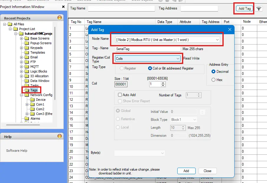
Creating Serial Modbus Tags
As before, we’ll create new tags associated with our Modbus node, and attach them to our screen like before.
Modbus Data on the HMI + PLC Unit
Now we have our devices configured to connect to each other, we’re able to receive our Modbus data from the PLC, and display that data on our HMC, but if we want to use this Modbus data in our HMC logic, there’s a few more steps we need to take.
Using Modbus Data in the HMC Logic
We have our Modbus data, but now we need to transfer that data to local HMC tags to use them in our HMC logic.
Instructions: Using Modbus Data in the HMC Logic
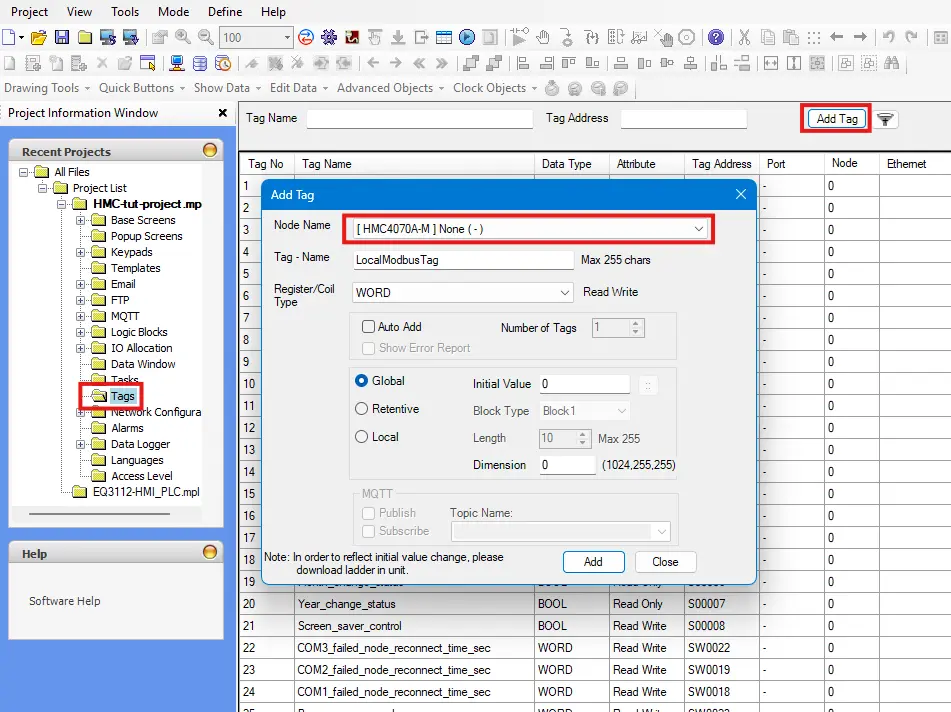
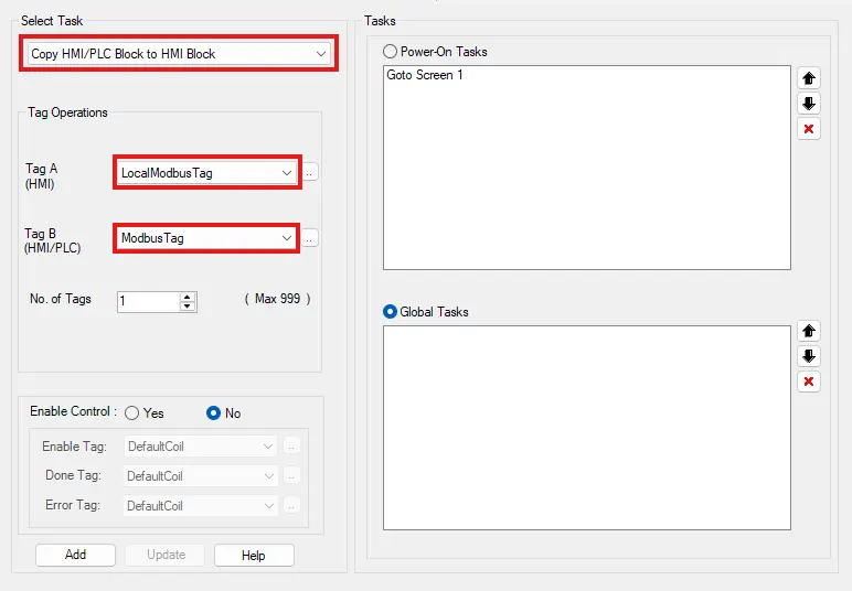
Create Local Copies of our Modbus Tags
We’ll start by creating tags on the local node (the one labeled after your HMC model) that match the type of the Modbus registers we want to transfer over
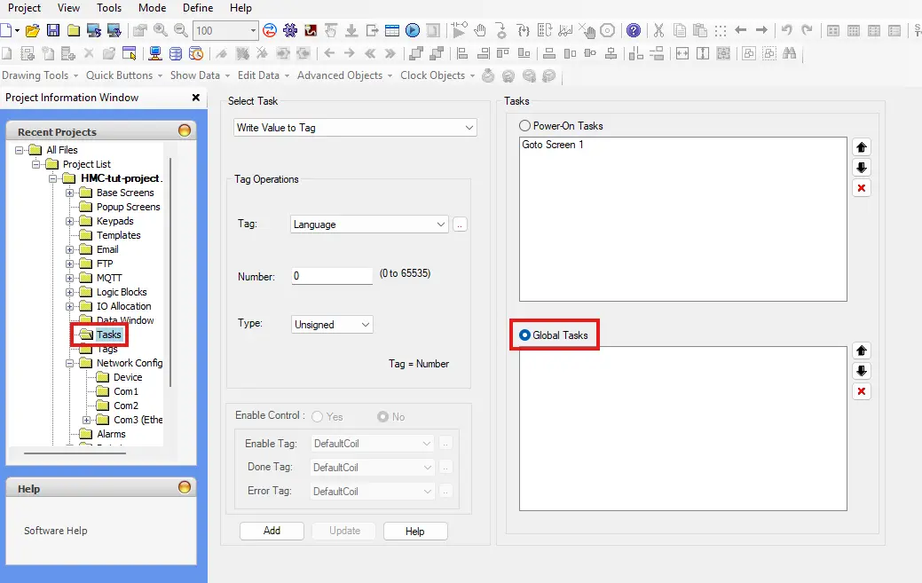
Creating a New Global Task
Now we’ll go to the “Tasks” page of our HMC project, and be sure to select “Global Tasks”
Transferring a “word” register
For a non-boolean “word” register, you’ll use the “Copy HMI/PLC Block to HMI Block” define which tags you’re transferring from and to, and click “Add” to add this task to your global task list
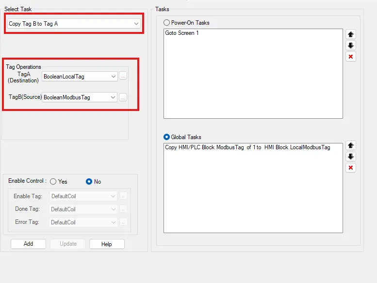
Transferring a boolean register
For a boolean register, you’ll instead use the “Copy Tag B to Tag A” task instead. “Tag B” is still the source, and “Tag A” is still the destination, but the idea is the same.
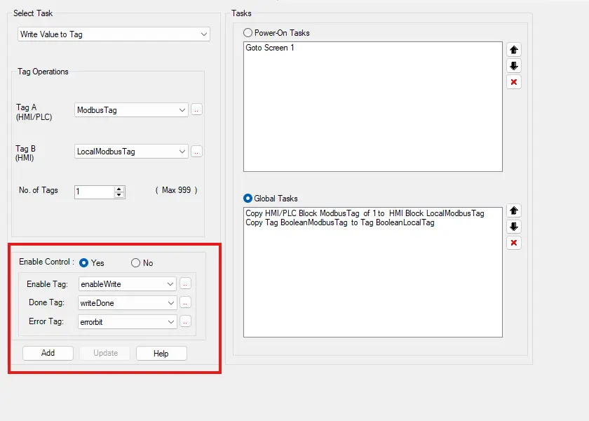
Writing to the PLC Modbus registers
If we need to write local tag values back to the PLC, we can do so, by setting up a global task going in the opposite direction. But if we have global tasks both reading from and writing to the same tags, we’ll want to use the control addresses of the global tasks and implement these in the logic to tell the HMC which direction the data is flowing.
Downloading our Project to the HMC
Now that we’ve finished our HMC project, we’re ready to download it to our device.
Instructions: Downloading our Project to the HMC
Navigating to the HMC System Settings
Now we’ll set our HMC’s IP address to something in the same subnet as our PLC. We’ll do this by pressing and holding the top-left corner of the HMC to go into the HMC system settings. Then we’ll click the “Network Settings” sidebar item.
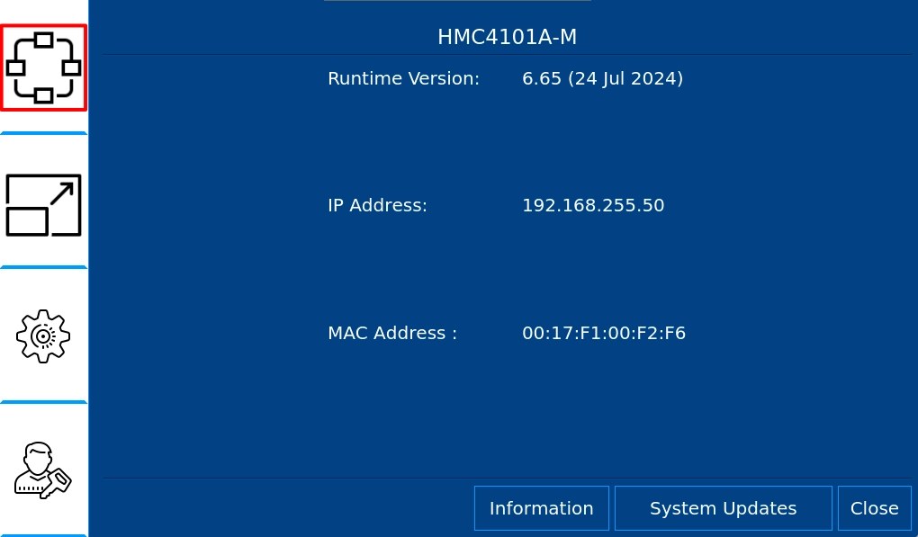
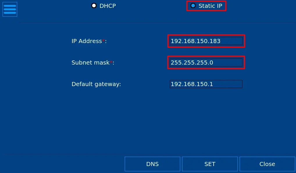
Configuring the HMC’s IP Address
In the Network settings, we’ll want to set our HMC to a static IP address, and change our HMC’s IP address and subnet mask to what we desire.
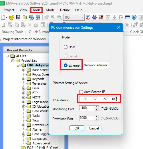
Preparing the Project for Download
Now we’ll go back into our MAPware-7000 project, navigate to “Tools > PC Communication Mode”, select “Ethernet” and change our base IP address to the IP address we just set our HMC to.
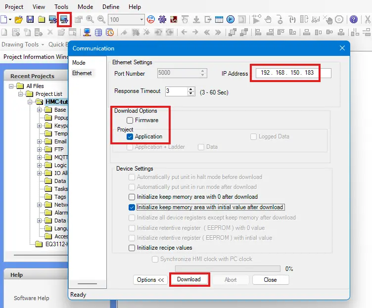
Downloading our Project
Now we’ll make sure our HMC is connected and powered on, and click the download button in MAPware-7000. After compiling the project, we’ll make sure the IP address on the download window is correct, and download our project.
Final Thoughts
Once we have our HMC in place and connected to all of our PLCs, we’ll be able to use this one combo unit to not only control each machine in our plant, but to also track metrics such as production speed, product counts, and uptime/downtime. This also allows us to monitor each machine for maintenance needs. When we integrate a Maple Systems HMC with a Modbus PLC, we’re able to keep the whole plant up and running smoothly.
Resources & Documentation
The following guides and documentation are specific to the hardware used in this integration tutorial and will help you with setup, configuration, and programming:
- MapleLogic (8.21.29)
- MapleLogic User Manual
- Maple Micro User Manual
- Maple Modular User Manual
- MAPware-7000
- MAPware-7000 Programming Manual
- MAPware-7000 Quickstart Guide
- Modbus Communications in MAPware-7000
Looking for additional learning resources? Explore our library of tutorials, example projects, and software tools to help you get the most out of your system:
Also, browse our Support Center for a complete list of installation guides, FAQs, and additional technical documentation.
About the Author
Trusted source for industrial automation & control solutions
Follow Maple Systems:
Share:


