Position control commands are used in motion control systems to regulate speed and position without relying on predefined motion paths, as outlined in the position instruction article.
In this guide, we focus on how PLC’s utilize flexible control commands to precisely adjust the positioning and speed of a machine component, such as a stepper motor. In addition, you’ll learn how to implement position instructions in your own system by following our demo project which uses an HMI, a PLC, and a stepper motor. For more detailed information on servo and stepper motor positioning, as well as other positioning instructions, refer to our previous article on stepper and servo motors.
1. Position Control Overview
Position control plays a critical role when precise position and speed are required, but the motion path isn’t predetermined. Unlike manual positioning or positioning instructions, position control commands offer greater flexibility because they allow you to adjust position and speed based on real-time feedback from sensors or controllers. For example, when you program robotic arms to inspect and assemble parts, you need the ability to adjust speed and position to adapt to varying workpieces or Enviromental changes. This flexibility is essential for accuracy and efficiency.
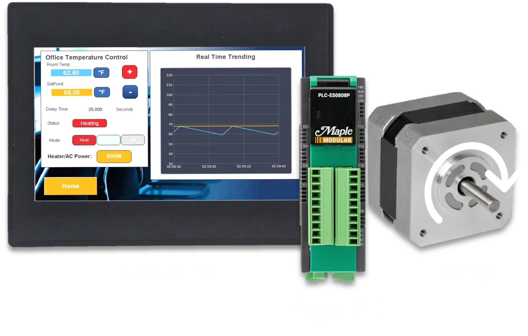
For this example, we’ll use a Maple HMI, a Maple PLC, a motor driver, and a stepper motor to build a simple motor positioning demo. The project includes visual elements, basic programming, and general positioning control design.

The position control portion of our demo uses two momentary buttons to select the distance for the position control command. It also includes another momentary button to initialize the motion command. As mentioned in previous articles, you don’t need an HMI for position control. However, using one provides a great way to visualize motor status and control PLC operations more effectively.
2. Position Control Command Codes
Before we create the application, let’s review the basics of position control. Unlike manual positioning or position instructions, position control doesn’t require any additional parameters to be configured in the position program window. Instead, it uses data registers specified by the user to adjust position and control movement in real time.
Position control lets users initiate various control motions, such as changing the current position address, adjusting speed, and more. The table below lists all the controls that can be initiated by the position control command. It also includes the command code for each operation and a brief description.

After choosing a command code we’ll determine what addresses need to be used. Because each operation has varying information requirements we’ll need to use the following table to properly populate the addresses being used.

3. MapleLogic Position Control
Positioning Control, or POSCTRL instruction, is used to conduct position control without using the position data. Position control can be used to change the current position address, change the speed parameter, inching operation, and more. In logic we’ll use the POSCTRL instruction and fill in our parameters:

n1: Slot Number (CPU= 0 [H0])
n2: Control Parameter (command codes shown in table 6)
n3: Result Flag
As an example, using the command code 3 and the device memory code of table 6, we can initiate the inching operation.

Above we can see that the D10 is the start of the position command code. So lets populate the following addresses before our POSCTRL instruction:

For our example, we will utilize the x-axis and the inching command (code 3). To set those we will move 1 into the D10 register and 3 into the D11 register. Now for the last parameter we’ll move a double word of 2000 into the D12 register. What this means is when the X01 register is turned ON the position command instruction will rotate the motor forward 2000 steps.
For more information and detailed instructions on other command codes see section 1.8.2 in the Position User Manual.
4. Download Software
Next, we will need to do is download our respective product software’s, EBPro for our HMI and MapleLogic for our PLC. Below are links to the direct download of each software:


After you have installed both software programs, we can start configuring and programming our demo application. The HMI and PLC programs used in this demo project can be downloaded at the bottom of the page.

Above is the Modbus mapping table we will use for our demo motor control project. For position control we will specifically use Modbus addresses 0x163, 0x164, and 0x165 to increment position, decrement position, and enable position control respectfully.
5. PLC Project
We are almost there! Below, you’ll see a simple scan program written in ladder logic to control the positioning of the stepper motor. As you can see, we use only a few contacts, timers for delays, set bits, and reset bits to operate the motor.
As mentioned earlier, position control supports various control features. In this example, however, we’ll use it to incrementally adjust the motor position by a specific amount.

As you can see on the first scan, we move the values into registers D100-D102. When we initiate the inching position control, D100 specifies that target axis, D101 holds the control code (inching), and D102 contains the control data. For simplicity, we’ll increase or decrease the number of pulses in register D102 by pressing Y102 or Y013. These buttons increase or decrease the value by 1000, respectfully.
6. HMI Project
The HMI Project requires three momentary buttons to increase and decrease the desired inching value and to trigger the position control command.
For setup instructions, refer to the previous positioning article and video tutorial. These resources show you how to establish communication between an HMI and PLC, and how to create various control and monitoring objects in the HMI software (EBPro).
Once communication is established, create three momentary push buttons using Modbus addresses 0x163, 0x163, and 0x165.

You can easily do this by clicking the “Set Bit” button, specifying the Modbus address, and selecting “Momentary” for the button. The button shown in figure 3 allows you to JOG forward. However, you can quickly change the address to 0x163 to increase the inching position instead.

Expanding on this, we can create a complete HMI project that can control all Modbus registers listed in Table 3.
7. Running the Applications
The last few steps are to wire up all devices, supply power, and download the respective projects to your HMI and PLC. Then run your applications!
In the above demonstration, the position control is shown from 0:13 to 0:30.
PLC and HMI Sample Projects:
You can download this file to access all the necessary projects required to recreate and run the positioning demo project described in this article
8. Video Tutorials

Introduction Stepper Motor and Servo Motor Positioning
This article covers the basics of positioning and speed control of a motor utilizing a Maple PLC and a Maple HMI for visualization. Learn how to use built-in positioning special programs.

Manual Positioning with Maple Systems PLCs
This article covers the basics of manual positioning utilizing a Maple PLC and a Maple HMI. Learn how to use JOG forward and backward using manual position commands.

Positioning Instructions with Maple System’s PLC
This article covers the basics of positioning and speed control of a motor utilizing a Maple PLC and a Maple HMI for visualization. This guide helps users set up position data to perform complex path instructions commonly used in robotics and CNC machining.

How to Set Up Maple PLC and Maple HMI using Modbus RTU and TCP Communications
This tutorial covers Modbus Communication via RTU and TCP between a Maple PLC and a Maple HMI. The PLC as a Slave device and the HMI as the master device.
Resources and Information
Sample Projects
We have created sample applications/projects and sample kits that demonstrate software features, give programming information for specific controllers, or demonstrate product capabilities.
Additional Resources
Download software, manuals, guides, sample projects, controller information sheets, cable drawings, CAD drawings, tech notes, or watch a tutorial video to get you started in our Support Center.
SCADA Systems
Maple Systems offers all the components to create own unique level of supervisory data acquisition control, from the simplest stand-alone machine to sophisticated multi-device networked production line(s) all the way to enterprise-level operations.
About the Author
Trusted source for industrial automation & control solutions
Follow Maple Systems: