How Do I Use Keypads in EZware-500?
Technical Note 1071
Applicable Model(s)
HMI500 Series
Title
How Do I Use Keypads in EZware-500?
Date
07/18/2005
Rev
03
P/N
0907-1071
Summary
When writing to a PLC register, a keypad may be required to allow the operator full flexibility when entering data. Some designers choose to place a fixed keypad on screen, but in some instances, it may be preferable to have the keypad popup only during data entry. For example, keypads take considerable screen space when placed on smaller HMI displays — space that could be used to display other information. Additionally, data entry may not always be available, so the keypad should be displayed only when access is allowed. This article describes how to use the default keypad or create a popup alphanumeric keypad using the ‘direct window’ or ‘function key popup’ objects.
A ‘keypad’ has numeric keys and some function keys such as ENTER, CLEAR & ESCAPE. It can be customized to include decimal points, the negative sign; even hexadecimal letters. The keypad can include the ASCII entry buffer and the MIN and MAX values for clearer feedback to the user. The keypad is typically used for ‘numeric input’ objects.
A ‘keyboard’ has numeric, letter, and punctuation keys. It usually includes some function keys such as ENTER, SPACE BAR, CLEAR & ESCAPE. It can be customized as the designer sees fit. The keyboard could also include the ASCII ‘entry buffer’ to give feedback to the user as the letters are typed. The keyboard is typically used for ‘ASCII input’ objects.
NOTE: In this Technical Note, fields requiring data entry are italicized.
Solution
With the introduction of Easy Builder version 2.5.0 and newer, a keypad has been added to the new project templates on window # 50. So whenever a new project is created, the following objects are added to facilitate a simple keypad popup without the user requiring to create one:
1.
On window #6 (the common window) is placed a ‘direct window’ object that reads LB:100 and will display window 50 if LB:100 is set to ON.
2.
On window #50 (Keypad) is placed a numeric style keypad. Under the keypad’s [ENTER] key and [ESC] key is placed a ‘set bit’ object that clears the bit LB:100 to OFF
3.
All the project designer has to do, is to add a ‘numeric input extend’ object, fill in the register
address to read & write, set the trigger-bit to LB: 9000, and add a shape of a button under the
{Shape} tab and select OK and place it on the window.
4.
Then add a ‘set bit’ object and fill in its write address to LB: 100. Set its attribute to ON. Select the {Shape} tab and click off any shape or bitmap so there is no shape attached. Now select OK and place this object on top of the numeric input.
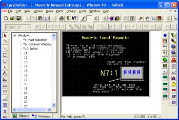
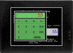
If you perform an off-line simulation, you can see now how a keypad will popup when the user
pushes on the numeric input button.
Creating Custom Keypads & Keyboards
The following steps will guide you through the creation of different popup keypads. This example will create a full screen window (Window #1) displaying three data registers. Three popup windows (Windows #2, #3, and #4) are created to hold a numeric keypad, an ASCII keypad, and a hexadecimal keypad. The predefined keypads from the Keypad group library are used; however, you may also create a custom keypad. When downloaded to the HMI, the full screen window is automatically displayed. The operator then touches the input register to be edited. The appropriate keypad window will be displayed, allowing data entry. When the [ENTER] key on the keypad is pressed, the keypad will automatically disappear.
Select HMI Model and PLC Type
1.
Start the EZware-500 application.
2.
Select the appropriate HMI model, (in this example, the HMI550H).
3.
Click OK.
4.
Select Edit—System Parameters… from the menu listings. The Set System Parameters dialog box is displayed.
5.
Under PLC type: select the PLC of your choice, (for this example, select MemoryMap_Master).
6.
Click OK.
Create the Data Registers
1.
Select Parts—ASCII Input from the menu listings. This displays the Create ASCII Input Object dialog box.
2.
Enter the following settings:
a.
In the Read Address section…
i.
Device Type – LW
ii.
Device Address – 0
iii.
No. of Words – 5
b.
In the Trigger Address section…
i.
Device Type – LB
ii.
Device Address – 9000
c.
Click OK.
3.
Use the mouse cursor to place the ASCII Input register on the left side of the screen of Window #10.
4.
Select Parts — Numeric Input from the menu listings. This displays the Create Numeric Input Object dialog box.
5.
Enter the following settings:
a.
In the Read Address section:
i.
Device Type – LW
ii.
Device Address – 5
iii.
No. of Words – 1
b.
In the Trigger Address section:
i.
Device Type – LB
ii.
Device Address – 9000
c.
Select the Numeric tab.
d.
In the Display section, select the Decimal option button.
e.
Click OK.
f.
Use the mouse cursor to place the Numeric Input register in the center of the screen of Window #10.
6.
Select Parts — Numeric Input from the menu listings. This displays the Create Numeric Input Object dialog box.
7.
Enter the following settings:
a.
In the Read Address section:
i.
Device Type – LW
ii.
Device Address – 6
iii.
No. of Words – 1
b.
In the Trigger Address section:
i.
Device Type – LB
ii.
Device Address – 9000
c.
Select the Numeric tab
d.
In the Display section, select the Hex option button.
e.
Click OK.
8.
Use the mouse cursor to place the Numeric Input register on the right side of the screen of
Window #10.
Create Three New Windows
1.
Select Window—Open Window from the menu listings. This displays the Open Window dialog box.
2.
Click New Window…
3.
Click Base Window. The Window Setting dialog box appears.
4.
Enter the following settings:
a.
Name – ASCII Keypad
b.
Window No. – 12
c.
Start Pos, X – 23
d.
Start Pos, Y – 148
e.
Size; Width – 325
f.
Size; Height – 110
g.
Click OK.
5.
You have now been returned to the Open Window dialog box. Select New Window…
6.
Select Base Window. The Window Setting dialog box appears.
7.
Enter the following settings:
a.
Name – Decimal Keypad
b.
Window No. – 13
c.
Start Pos, X – 220
d.
Start Pos, Y – 124
e.
Size; Width – 240
f.
Size; Height – 240
g.
Click OK.
8.
You are once again returned to the Open Window dialog box. Select NEW WINDOW…
9.
Click BASE WINDOW. The Window Setting dialog box appears.
10.
Enter the following settings:
a.
Name – Decimal Keypad
b.
Window No. – 13
c.
Start Pos, X – 220
d.
Start Pos, Y – 124
e.
Size; Width – 240
f.
Size; Height – 240
g.
Click OK.
11.
Click Close…
Create the ASCII Keypad
1.
Select Library >> Shape >> Call Up Library From the menu listings. This displays the Shape Library dialog box.
2.
Click SELECT LIB…
3.
Select captions.slb from the Library subdirectory listings.
4.
Click Open.
5.
Click SELECT LIB…, then select button1.slb from the Library subdirectory listings.
6.
Click Open.
7.
Click OK.
8.
Select Window—Open Window from the main menu. This displays the Open Window dialog box.
9.
Highlight Window #12 (ASCII keypad) and click OPEN. Window #12 should now appear.
10.
Select Library—Group—Call Up Library from the menu listings. This displays the Group Library dialog box.
11.
Click SELECT LIB…
12.
Select keypad.glb from the Library subdirectory listings. Then click Open.
13.
Click on the 5: alpha3 library element and then click PLACE…
14.
Use the arrow keys on your computer to position the ASCII keypad correctly in place.
15.
Select Parts—Function Key from the menu listings. This displays the Create Function Key Object dialog box.
16.
Enter the following settings:
a.
Description – Close the ASCII Keypad
b.
Select the Close Window option button.
c.
Click OK.
d.
Move the mouse cursor so that the outlined box is over the ENTER key on the keypad.
e.
Click to place.
f.
Resize the white-outlined box using the resizing handles so that it covers the ENTER
key only.
g.
It is necessary to place the Function Key object underneath the ENTER key. To do so,
select Edit >> Layer >> Bottom Layer from the menu listings while the Function Key
object is still highlighted.
Create The Decimal Keypad
1.
Select Window—Open Window from the menu listings. This displays the Open Window dialog box.
2.
Using the mouse, highlight Window #13 (Decimal keypad), and then click OPEN. Window 13 will appear.
3.
Select Library >> Group >> Call Up Library from the menu listings. This displays the Group Library dialog box.
4.
In the Library Name: field, select Keypad.
5.
Click on the 2: num2 library element, and then click PLACE.
6.
Use the arrow keys on your computer to position the Decimal keypad correctly in place.
7.
Select Parts—Function Key from the menu listings. This displays the Create Function Key Object dialog box.
8.
Enter the following settings:
a.
Description – Close the Decimal Keypad
b.
Select the Close Window option button.
c.
Click OK.
9.
Move the mouse cursor so that the black-outlined box is over the ENT key on the keypad.
10.
Click to place.
11.
Resize the white-outlined box to resize using the resizing handles so that it covers only the ENT key.
12.
It is necessary to place the Function Key object underneath the ENT key. To do this, select
Edit >> Layer >> Bottom Layer so from the menu listings while the Function Key object is still
highlighted.
Create the Hex Keypad
1.
Select Window—Open Window from the menu listings. This displays the Open Window dialog box.
2.
Using the mouse, highlight Window #14 (Hex keypad), and then click OPEN. Window #14 will appear.
3.
Select Library >> Group >> Call Up Library from the menu listings. This displays the Group Library dialog box.
4.
In the Library Name: field, select Keypad.
5.
Click on the 3: hex1 library element, and then click PLACE…
6.
Use the arrow keys on your computer to position the Hex keypad correctly in place.
7.
Select Parts—Function Key from the menu listings. This displays the Create Function Key Object dialog box.
8.
Enter the following settings:
a.
Description – Close the Hex keypad
b.
Select the Close Window option button.
c.
Click OK.
9.
Move the mouse cursor so that the outlined box is over the ENT key in the keypad.
10.
Click to place.
11.
Resize using the resizing handles so the box it covers only the ENT key.
12.
The Function Key object must be placed underneath the ENT key. To do so, select Edit >> Layer >> Bottom Layer from the menu listings while the Function Key object is still highlighted.
You have now created four screens. The first screen displays three input registers. The second
screen is used to display the ASCII Input keypad. The third screen displays the Decimal keypad and
the fourth screen displays the Hex keypad.
Use Function Key to Activate Keypads
1.
Return to Window #10 (initial screen) by selecting Window—Window 10 from the menu listings.
2.
Select Parts—Function Key from the menu listings. This displays the Create Function Key dialog box.
3.
Enter the following settings:
a.
Description – Display ASCII Keypad
b.
Select the Popup Window option button.
c.
Window No. – 12
4.
Click OK.
5.
Use the mouse cursor to overlay the object where the ASCII Input register is located on the left side of the screen.
6.
Resize the white-outlined box to the same size as the ASCII input register using the resizing handles.
7.
Select Parts—Function Key from the menu listings. This displays the Create Function Key Object dialog box.
8.
Enter the following settings:
a.
Description – Display Decimal Keypad
b.
Select the Popup Window option button.
c.
9.
Click OK.
10.
Use the mouse cursor to overlay the object where the Decimal Input register is located in the center of the screen.
11.
Resize the white-outlined box to the same size as the Decimal Input register using the resizing handles.
12.
Select Parts—Function Key from the menu listings. This displays the Create Function Key Object dialog box.
13.
Enter the following:
a.
Description – Display Hex Keypad
b.
Select the Popup Window option button
c.
Window No. – 14
14.
Click OK.
15.
Use the mouse cursor to overlay the object where the Hex Input register is located on the
right hand side of the screen.
16.
Resize the white-outlined box to the same size as the Hex Input register using the resizing
handles.
Save, Compile, and Simulate
1.
Select File >> Save from the menu listings.
a.
File Name – Name the Project
b.
Click Save.
2.
Select Parts—Function Key from the menu listings. This displays the Create Function Key dialog box.
3.
Click Compile.
4.
After the computer has compiled the project, click CLOSE.
5.
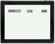
Select Tools—Offline Simulation from the menu listings. The offline simulator will appear:
6.
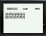
Use the mouse cursor to touch the blank ASCII register on the left. The ASCII keypad will automatically appear:
7.
Enter ABCDE. The value is entered into the register.
8.
Press the ENTER key. The ASCII keypad automatically closes.
9.
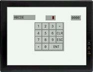
Use the mouse cursor to touch the blank Decimal register in the middle. The Decimal keypad will appear:
10.
Enter 1234. The value is entered into the register.
11.
Press the ENT key. The Decimal keypad automatically closes.
12.
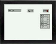
Use the mouse cursor to touch the blank Hex register on the right. The Hex keypad will
appear:
13.
Enter ABCD. The value is entered into the register.
14.
Press the ENT key. The Hex keypad automatically closes.
Using the Built-in Numeric Keypad in EasyBuilder
An alternative to using the numeric keypads from the EasyBuilder libraries is using the keypad
located in Window 50 of the EasyBuilder software.
Create the Data Registers
1.
Select Parts—Numeric Input from the menu listings. This displays the Create Numeric Input Object dialog box.
2.
Enter the following settings:
a.
In the Read Address section:
- Device Type — LW
- Device Address — 5
- No. of Words — 1
b.
In the Trigger Address section:
- Device Type — LB
- Device Address — 9000
c.
Select the Numeric tab.
d.
In the Display section, select the Decimal option button.
e.
Click OK.
f.
Use the mouse cursor to place the Numeric Input register in the center of the screen of Window #10.
3.
Select Parts >> Set Bit from the menu listings. This displays the Set Bit Object dialog box.
4.
Enter the following settings:
a.
In the Write Address section:
- Device Type — LB
- Device Address — 100
- Attribute – Style — ON
5.
Place the Numeric Input Object and the Set Bit Object on top of each other.
Setup the Common Window
1.
Select Window—Open Window from the menu listings. This displays the Open Window dialog box.
2.
Highlight “Common Window” and click OPEN.
3.
This window has already been configured to display a Direct Window Object shown as a
white outline of a square. Its settings should be:
a.
In the Read Address section:
- Device Type — LB
- Device Address — 100
- Window No. — 50
4.
Use the “Save, Compile, Simulate” directions shown above.
5.
Once in Simulation mode, click on the Numeric Input object. The Decimal keypad should appear.
6.
Enter 1234. The value is entered into the register.
7.
Press the ENT key. The Decimal keypad automatically closes.
More Information
In the example above, notice that Device Type LB9000 was used for the ‘Trigger Address’ on the Numeric and ASCII Input objects. The trigger address controls write access. If the coil is ON, then write access is allowed. If the coil is OFF, then the operator is unable to write to that register even if he touches the register. LB9000 is an internal memory coil of the HMI500 that is always ON.
For more information regarding custom keypads, please refer to Chapter 8, Using and Creating Keypads in the HMI500 Series Installation and Operation Manual that is supplied on CD ROM with the EZware-500 configuration software.
