Barcode Scanner
Technical Note 5079
Applicable Model(s)
HMI5000 Series
cMT Series
Title
Barcode Scanner
Date
01/20/2023
Rev
03
P/N
0907-5079
Summary
This document illustrates how to configure the HMI5000/cMT Series products to communicate with USB and serial barcode scanners.
Solution
The barcode.(e)mtp project referenced in this document is available for download in the Support Center under Sample Projects on the Maple Systems website.
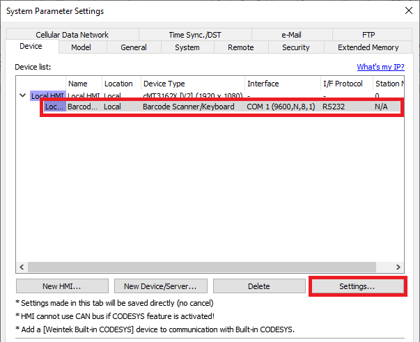
First, configure the Barcode Device communication settings. To add/modify the barcode scanner communication settings in click Home > System Parameters. On the Device tab, select the Barcode device and select Settings… to access the configuration settings.

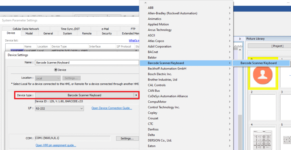
If adding a Barcode scanner to an existing project or creating a project from scratch, select New on the Device tab and configure the following:

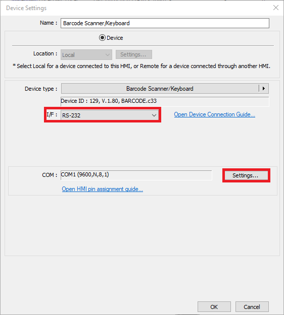
Next, select the interface type (RS232 or USB) then click the Settings button.

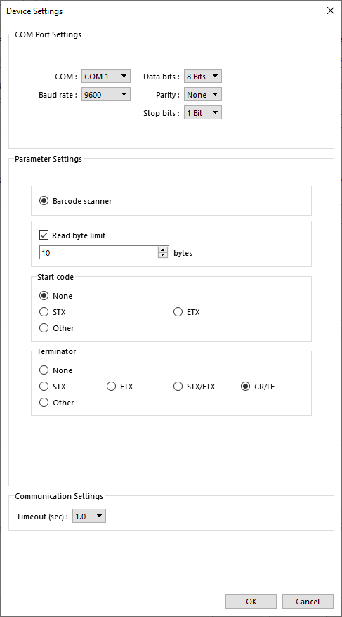
The following dialog will be displayed to configure the scanner:

Barcode Device/Keyboard
In Barcode device mode, the protocol accepts 24 bytes of data maximum per read. In Keyboard mode, there is no maximum accepted data. Use Keyboard mode if you need to read more than 24 bytes at a time.
Read Byte Limit
When checked, the HMI will stop reading barcode data after the specified number of bytes, even if the specified terminator has not been detected.
Use a Start Code
When checked, the HMI will not start processing data from the barcode device until the specified character has been detected. Enter the decimal ASCII value of the character.
Terminator
Select the character that marks the end of the barcode data.
CR/LF
Data ends at a Carriage Return (CR) or Line Feed (LF).
STX/ETX
Data ends at a Start of Text (STX) or End of Text (ETX).
Other
Specify the decimal value of the character’s ASCII code.
None
No terminator is used. The data ends at the end of the transmission, or when the Read Byte Limit is reached.
The Barcode Device supports data types:
| Address Type | Device Type | Address | Description |
|---|---|---|---|
| Bit | FLAG | FLAG 0 | Indicates the status of data read. When reading data, FLAG 0 is set OFF and will return ON when finish reading successfully. |
| RESET | RESET 0 | Clears the data of BARCODE and RESULT registers when set ON. | |
| CONNECT_STATUS | CONNECT_STATUS 0 | Indicates whether the barcode reader (USB interface) is connected. When the status is ON, the barcode reader is connected. | |
| Word | BARCODE | BARCODE 0 | Number of bytes read. |
| BARCODE 1 – n | Stores the data read. | ||
| RESULT | RESULT 0 | Indicates the result of data reading. The following codes can appear: 0x00: Waiting to read data. 0x01: Data successfully read. 0x02: Invalid data format. 0x03: Exceeds the number of bytes specified in [Read byte limit]. 0x04: The data does not identify with the specified start code. 0x05: The data does not identify with the specified terminator. |
The following is a screenshot from the barcode.emtp project:

Scan Complete
This is a Bit Lamp that monitors the bit FLAG0. Since FLAG0 triggers a macro that ultimately resets FLAG0, this indicator lights briefly on each scan.
Number of Bytes Received
This is a Numeric Display that monitors the register BARCODE0. When the scan has finished, BARCODE0 contains the number of bytes received from the barcode device..
Data Received
This is an ASCII Display that monitors the register 32 words of data starting at register BARCODE1. The ASCII Display object properly decodes the data and displays it as text.
Raw Data
These are a series of Numeric Display objects, starting with address BARCODE1. Each display shows 16 bits of raw ASCII data received from the barcode device. Since each byte from the barcode device occupies 8 bits, each display object shows two characters received from the barcode device. The data is shown in Hexadecimal format. Note that the byte order is reversed!
The following table illustrates how the barcode.(e)mtp file reads and displays data from the barcode scanner. The Scanned Digit column displays the values from the Data Received field. The Barcode Register column indicates which register is displaying the raw data for each digit, and the Register Data column displays the raw hexadecimal value for the two digits referenced in the Scanned Digit column.
| Scanned Digit | Barcode Register | Register Data (Hex) | Low or High Byte (ASCII Code in Hex) |
| 3 | BARCODE1 | 3933 | Low (33) |
| 9 | BARCODE1 | High (39) | |
| 8 | BARCODE2 | 3238 | Low (38) |
| 2 | BARCODE2 | High (32) | |
| 0 | BARCODE3 | 3830 | Low (30) |
| 8 | BARCODE3 | High (38) | |
| 6 | BARCODE4 | 3036 | Low (36) |
| 0 | BARCODE4 | High (30) | |
| 8 | BARCODE5 | 3838 | Low (38) |
| 8 | BARCODE5 | High (38) | |
| 0 | BARCODE6 | 3830 | Low (30) |
| 8 | BARCODE6 | High (38) |
When the Scan Complete signal (FLAG0) turns on, a macro runs that copies the scanned data from the BARCODE registers to a series of Local Words. The macro is listed below:
macro_command main()
bool off = 0
short data[32]
// get actual data received from barcode device
GetData(data[0], “Barcode Device”, BARCODE, 1, 32)
// write the data to local registers
SetData(data[0], “Local HMI”, LW, 1, 32)
// turn off the Scan Complete bit
SetData(off, “Barcode Device”, FLAG, 0, 1)
end macro_command
