IP Addresses of an HMI and a PC
Technical Note 5077
Applicable Model(s)
HMI5000 Series
cMT Series
Title
IP Addresses of an HMI and a PC
Date
09/28/2022
Rev
02
P/N
0907-5077
Summary
This document describes the process of setting the IP address of an HMI and the development PC to allow Ethernet communications.
Solution
NOTE: Configuring IP addresses while connected to an established network can interrupt communication if care is not taken. Consult a networking specialist before proceeding.
1.
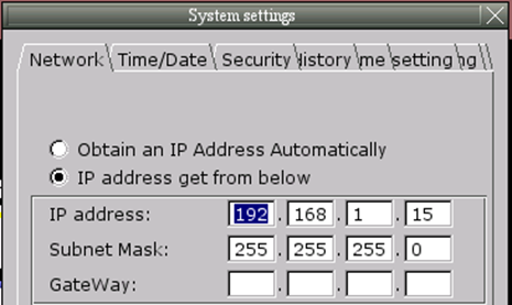
HMI Series Models: Set the IP address of the HMI by selecting the System Setting bar on the HMI in the bottom right corner, enter the local password (default: 111111), change the setting on the Network tab to “IP address get from below”, and enter an IP address and subnet mask for the HMI (for example, set the IP address to 192.168.1.15; the subnet mask is generally 255.255.255.0).

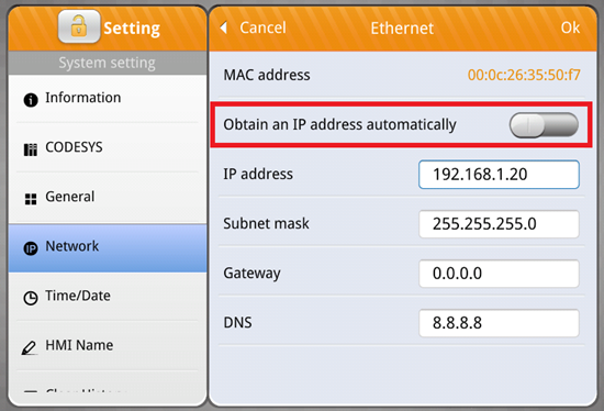
cMT Series Models: Tap on the orange System Setting button that is in the top left corner by default, and login by tapping the lock icon. Enter the local password (default: 111111), select the Network tab, and change the “Obtain an IP address automatically” slider so that you may now enter a custom IP address as described above.

2.
Set the IP address of the PC. This procedure will vary depending on the operating system on the PC. For information on where to find the IP settings on the PC, use a search engine to find “Set IP address in Windows xx.” The xx can be replaced by 7, 10, 11 etc.
3.
Change the setting on the Internet Protocol Version 4 dialog box to “Use the following IP address” and enter an IP address for the PC with the first three sets of numbers matching those of the HMI and a matching subnet mask (for example, set the IP address to 192.168.1.10; set the subnet mask to 255.255.255.0)
4.
Connect a Crossover Ethernet cable between the Ethernet port of the PC to the HMI Ethernet port or connect the PC and HMI to an Ethernet switch via straight through Ethernet cable
5.
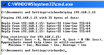
Ping the HMI from the PC to verify the connection; Open Command Prompt and enter “ping 192.168.1.15” (the IP address of the HMI); if the HMI is found the command prompt will display the following:

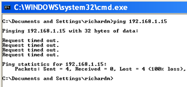
If the Ping function fails, check the Ethernet cable for proper connection and wiring and then check the IP addressing of the devices. If the device is not found the command prompt will display the following:

6.
Configure your PLC with an IP address in the same range and the same subnet mask (e.g. 192.168.1.15 for the HMI and 192.168.1.20 for the PLC; the first three sets of numbers need to match for the devices to communicate properly with the subnet mask set to 255.255.255.0); connect the PLC to the HMI direct with a crossover Ethernet cable or through the switch with a straight through Ethernet cable.
At this point your network should be configured and able to communicate. Download projects to the HMI and PLC that will communicate with each other and verify that there is not a “PLC No Response” message. Disconnect the Ethernet cable to cause the “PLC No Response” message to appear to verify that communication is operating when the cable is connected.
