Skills you’ll gain: Configuring an Analog Input Module and using ladder diagram logic to read 0-10V and 4-20mA from a Pressure Sensor.
Software Required
Hardware Required
- Maple Modular PLC’S – Any Maple Modular PLC can be used.
- Maple Micro PLC’S – Any Maple Micro PLC can be used.
Keep in mind that the Maple Micro PLC’s have built in Analog I/O. To see the Analog I/O wiring, please review the documents in the “Resources & Documentation” section of this tutorial.
Wiring and Circuit Design
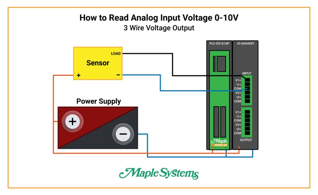
Analog Input 0-10V
SENSOR:
Orange Wire: Positive to + Power Supply
Black Wire: Load to V1+
Blue Wire: Negative to COM
POWER SUPPLY:
Orange Wire: Positive to + on PLC and + on I/O
Blue Wire: Negative to – on PLC and – on I/O
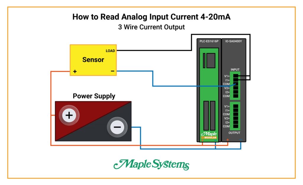
Analog Input 4-20mA
SENSOR:
Orange Wire: Positive to + Power Supply
Black Wire: Load to I1+ and jumper to V1+
Blue Wire: Negative to COM
POWER SUPPLY:
Orange Wire: Positive to + on PLC and + on I/O
Blue Wire: Negative to – on PLC and – on I/O 4-20mA
Software Code
FROM Application Instruction
A FROM instruction reads a value of buffer memory and saves its value to the device address.

Buffer Memory
This is the memory in an I/O Module that stores the digital signals converted by the I/O Module and also records set values in the currently operating I/O module. Analog conversion values which is stored in buffer memory 0 ~ 1 are stored into the CPU memory to be used for a program using the FROM application command.

4-20mA Pressure Sensor Reading
I/O Module Input Channel 1 is configured to 4-20mA with a value range set at 0-16000
Reading 15.041mA at 69.00%
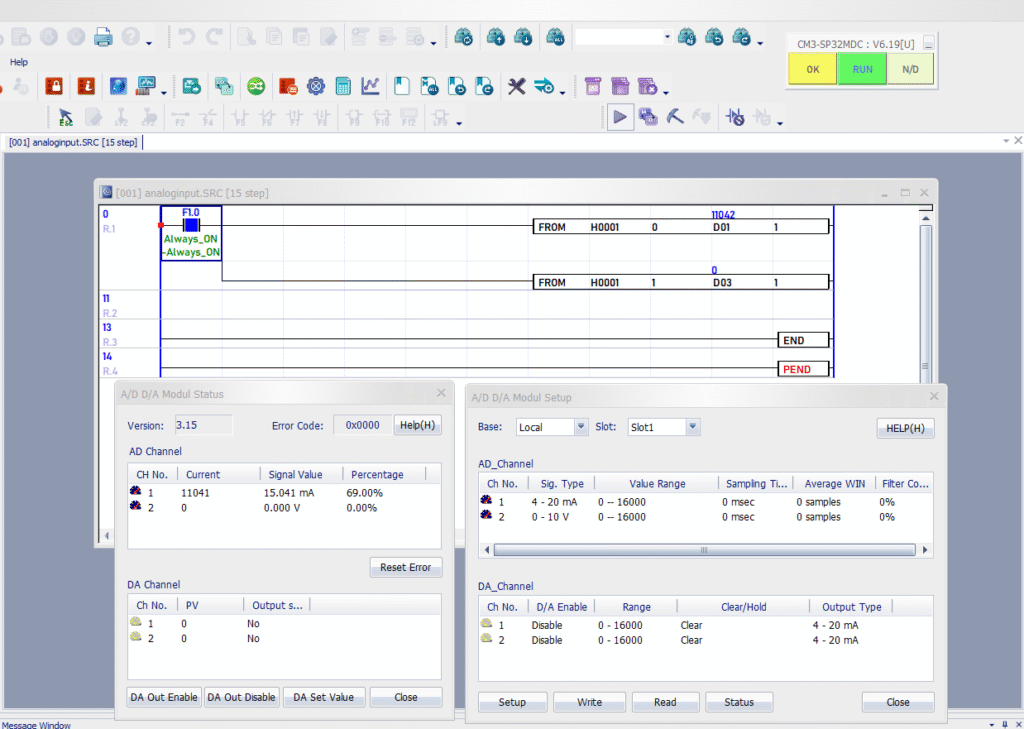
If F10 is ON, the FROM instruction copies value (11042) of buffer memory 0 from slot number (H0001) and saves (11042) to D01.
0-10V Pressure Sensor Reading
I/O Module Input Channel 2 is configured to 0-10V with a value range set at 0-16000.
Reading 5.004 V at 50.04%
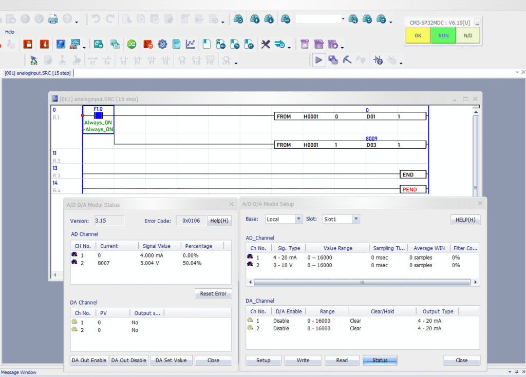
If F10 is ON, the FROM instruction copies value (8009) of buffer memory 1 from slot number (H0001) and saves (8009) to D03.
Another option to configure your I/O module is to use the “LD convert” option. To get information on this, please refer to the “How to Configure your I/O Modules Virtually and Convert your Ladder Diagram” Tutorial page.
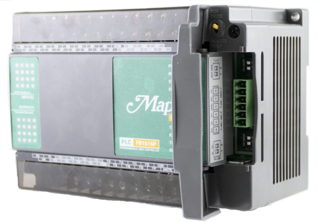
If you are using a Maple Micro PLC, in order to read the analog input, you will need to change the dipswitch from voltage to current to get those values. The dipswitch is located under a cover on top of the PLC.
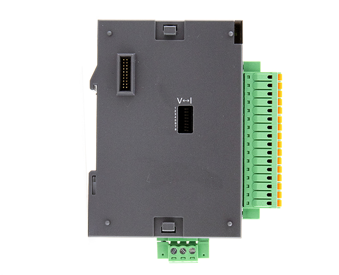
Also, if you are using a Maple Modular PLC with an IO-SA0800Y 8CH Analog Current/Voltage input module, you will need to change the dipswitch from voltage to current. This is located on the side of the I/O Module.
Sample Project
The project shown above was designed for the specific hardware mentioned at the beginning of the tutorial and is intended to provide you guidance when programming your unit. If you are using models other than the ones specified in this sample project, similar steps can be duplicated within your own project.
Download MapleLogic Sample Project
Resources & Documentation
Maple PLC/MapleLogic Resources
- MapleLogic User Manual
- Maple Modular User Manual
- Maple Micro User Manual
- Analog IO Module User Manual
More Tutorials Sample Projects
See our Support Center for a complete list of Quick Start and Installation Guides
About the Author
